

Short answer
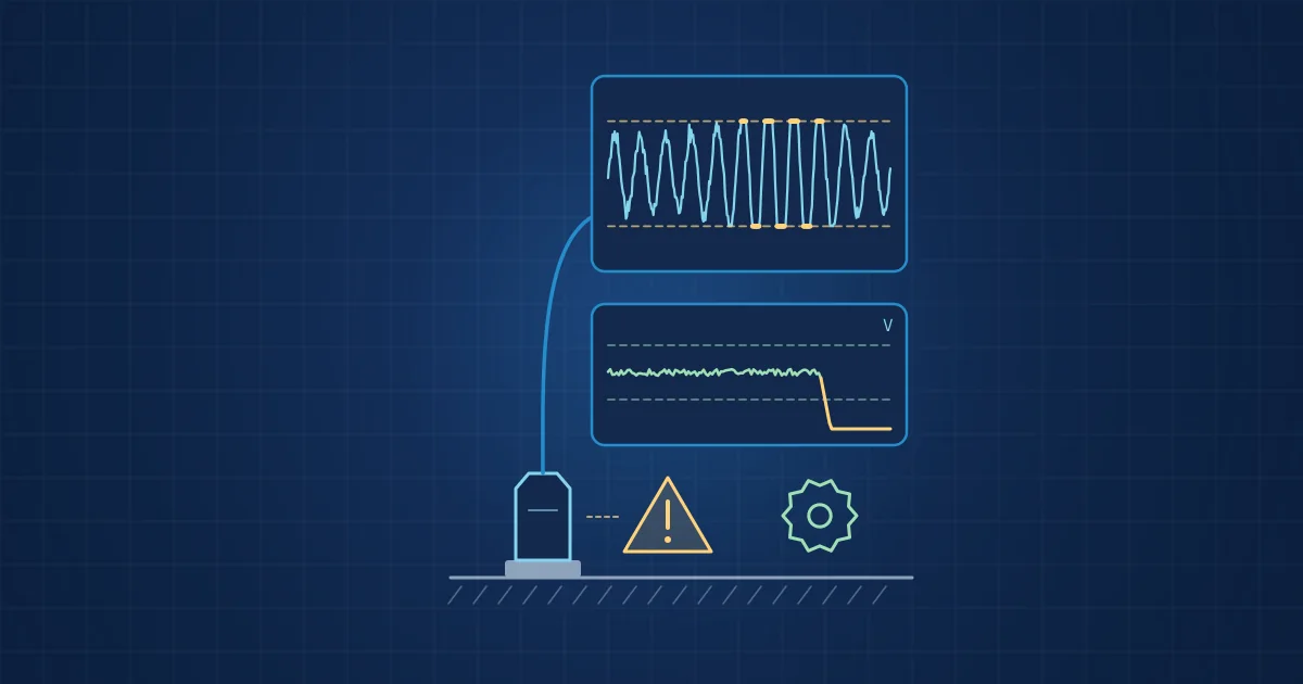
Self-monitoring sensors continuously check the quality of their own signal, for example bias voltage, noise floor, clipping, dropouts and plausibility against other sensors. When a check fails, they raise a sensor alert and mark the affected data, so a loose mounting, damaged cable or saturated input is reported as a sensor problem instead of reaching the fault models as a machine fault.
Key takeaways
- Most models cannot tell a sensor fault from a machine fault, because both change the signal; the distinction has to be made before the model runs.
- Many sensor faults have clear electrical or statistical signatures, such as a bias voltage at supply level for an open circuit or 0 V for a short in IEPE accelerometers.
- A self-monitoring sensor reports a health state with every record, so downstream models can skip invalid data and maintenance gets a sensor ticket, not a machine alarm.
- Gaps from dropouts or power loss should be logged and reported explicitly, because missing data silently treated as normal is its own kind of false result.
- ISO 17359 sets out the general procedures for setting up a condition monitoring programme, and sensor health checks belong in that set-up rather than being added after the first false alarms.
Self-monitoring sensors address one of the most common reasons condition monitoring systems lose the trust of the people who use them: false alarms caused by the sensor rather than the machine. An accelerometer that has worked loose produces a signal with new resonances and odd impacts. A cable with a damaged shield picks up mains hum. To an anomaly detector, both look abnormal, because they are. The model is right about the signal and wrong about the machine.
This article covers the typical sensor faults, the signatures that reveal them and how to build sensor health into the data path so that sensor faults never become fault statistics.
What is a self-monitoring sensor?
A self-monitoring sensor is a sensor, or a sensor with its local electronics, that evaluates the quality of its own measurement continuously and reports the result alongside the data. We call sensors with this capability, in whole or in part, cognitive sensors. The output is not just "acceleration" or "sound pressure", but "acceleration, and here is how far you can trust it".
Self-monitoring is distinct from calibration. Calibration establishes the sensor's accuracy under controlled conditions at a point in time. Self-monitoring checks, during operation, that nothing has changed since: the sensor is still attached, powered, connected, within range and delivering data without gaps.
Why sensor faults become false alarms
Condition monitoring models are built to react to change. Anomaly detectors, in particular, flag anything that differs from the normal data they were trained on, as described in the model ladder. A sensor fault is a change. Unless the system knows the sensor is at fault, the change is attributed to the machine.
The cost is not just one false alarm. Each one costs a maintenance visit and some credibility. After a few, operators start ignoring alerts, and the one real fault is missed. Sensor faults also contaminate training data: if recordings with a loose sensor are labelled as a fault class, the next model learns the loose sensor. That is a shortcut of exactly the kind discussed in validating industrial AI models.
Common sensor faults and their signatures
Many sensor faults have recognisable signatures. Some are electrical, some statistical, some only visible in comparison with other sensors.
| Fault | Typical signature | How it can be detected |
|---|---|---|
| Open cable or connector (IEPE) | Bias voltage at supply level, no signal | Bias voltage monitoring |
| Short circuit (IEPE) | Bias voltage at 0 V | Bias voltage monitoring |
| Ground loop or poor shielding | Mains frequency and harmonics, erratic bias, spikes in the waveform | Line-frequency band energy, bias stability |
| Loose or degraded mounting | Lower mounted resonance, changed high-frequency response, rattling impacts | Resonance tracking, high-band ratio, comparison with neighbouring sensors |
| Saturation or clipping | Flattened peaks, waveform truncated on one side | Clipping counter, peak against full scale |
| Dead or stuck sensor | Variance near zero, constant value | Flatline detection on variance or noise floor |
| Gain or offset drift | Slow change of level without change in spectral shape | Trend against reference or redundant sensor |
| Data dropouts | Missing samples, gaps in counters or time stamps | Sample counters, gap detection |
| Camera degradation | Blur, contamination, exposure shift | Sharpness and brightness statistics in a reference region |
The IEPE figures come from Wilcoxon's application note on troubleshooting accelerometer installations. IEPE (integrated electronics piezo-electric) sensors are powered by a constant current over the signal cable, and their output sits on a DC bias. The note states that when "the measured BOV equals the supply voltage, the sensor amplifier is disconnected or reverse powered", that "a measurement of 0 volts indicates a short in the system", and that harmonics of the AC line frequency usually indicate interference from motors, power lines and other emissive equipment. It also warns that mounting resonance can falsely appear as high-frequency gear mesh or bearing faults, especially with probe tips and magnets.
Mounting deserves particular attention. PCB Piezotronics' mounting guidelines explain that adding mass, such as an adhesive or magnetic mounting base, "lowers the resonant frequency" and that softer connections reduce the upper frequency limit. A sensor that loosens over months changes its frequency response gradually, which looks to a model like a slowly developing fault.
Checks a sensor can run on itself
Self-monitoring combines several layers of checks, each cheap on its own.
- Electrical checks. Supply voltage, bias voltage for IEPE sensors, current draw. These catch cable and connector faults immediately.
- Built-in self-test. Some sensors can stimulate themselves. Analog Devices lists a "complete electromechanical self-test" for the ADXL1002 MEMS accelerometer, the sensor used in our Vibration Node. Running such a test periodically, when the machine allows, confirms the sensing element is alive.
- Signal statistics. Noise floor, variance, peak relative to full scale, number of clipped samples, energy at mains frequency and its harmonics. These are computed per segment alongside the normal features and cost very little.
- Data integrity. Sample counters, expected sample counts per segment, gaps in time stamps, clock offset. These detect dropouts and buffer overruns that otherwise disappear silently.
- Cross-sensor plausibility. A machine fault usually shows up in more than one place: two accelerometers on the same bearing housing, or vibration and sound at the same frequency. A change seen by only one sensor, on a channel where its neighbours see nothing, is more likely a sensor problem. This is one practical benefit of multimodal sensing.
- Reference comparisons. For cameras, sharpness and brightness in a fixed region that should not change; for thermal imagers, a reference surface of known behaviour.
None of these checks needs AI. They are rules with thresholds, and they are easier to explain and verify than a model. Where rules are not enough, a small dedicated model trained to recognise sensor faults, separately from the machine fault models, is the next step.
Designing the data path around sensor health
Detecting a sensor fault is only useful if the rest of the system acts on it. A robust design has these properties:
- Every record carries a health state. For example valid, degraded or invalid, with the reason. It is stored with the data, not only shown on a screen.
- Fault models are gated. Segments marked invalid do not reach the anomaly detector or classifier. Degraded segments are processed but flagged.
- Sensor alerts are a separate category. They go to whoever maintains the measurement system, with a clear cause such as "bias at supply voltage, check cable at sensor V3".
- Gaps are explicit. Missing data is logged, alerted and reported, never interpolated or quietly skipped. A monitoring system that reports "normal" for a period in which it recorded nothing is giving a false result.
- Health history is kept. A sensor that degrades slowly is visible only in its trend. Keeping health statistics over time also helps judge whether old recordings are fit for training.
- Training data is filtered. Recordings with invalid health states are excluded or labelled as such before model training.
Timing is part of health too. If a node's clock drifts relative to the hub, events from different sensors no longer line up, and a cross-sensor plausibility check can draw the wrong conclusion. We discussed why in time-stamping multimodal sensor data.
What the standards say
Sensor health is not an optional extra in condition monitoring practice. ISO 17359, the general guideline for condition monitoring and diagnostics of machines, gives guidelines for the general procedures to be considered when setting up a condition monitoring programme. Every later step of such a programme, from trending to alarms, relies on measurements that can be trusted, so sensor health checks belong in the set-up from the start. In the processing model of ISO 13374-1, data acquisition is the first block; a paper on e-maintenance frameworks describes this block as producing digital records with values and descriptive metainformation like time stamps and quality. Quality is meant to travel with the data from the start.
A sensor health checklist
- Every sensor channel reports electrical health where the interface allows it.
- Per-segment statistics include noise floor, clipping count and mains-frequency energy.
- Sample counters and time stamps are checked for gaps on every segment.
- Built-in self-tests are scheduled where available.
- Health states are stored with each record and gate the fault models.
- Sensor alerts and machine alerts are routed separately.
- Mounting method and position are documented, and a reference recording is taken after installation.
- Training data sets exclude or explicitly label segments with invalid sensor health.
How NeuroControls approaches this
In our systems today, signal health and dropouts are flagged at the edge with the data, so gaps and problem segments are visible in the record instead of passing silently into analysis. The principle is described on our cognitive sensors page.
The recording software applies the same idea to the data path. A node's clock offset is measured continuously and written into every record, with its uncertainty. After a power loss, the gap is logged, alerted and reported, and recording resumes by itself. The operator dashboard on the hub shows live status and alerts over the local network; details are on our software page.
Frequently asked questions
What is a self-monitoring sensor?
A self-monitoring sensor continuously evaluates the quality of its own measurement and reports it alongside the data. Typical checks include supply and bias voltage, noise floor, clipping, dropouts and plausibility against neighbouring sensors. The result is a health state for each record, so downstream systems know whether the data can be trusted before any fault model sees it.
How do you detect a loose accelerometer?
A loosening accelerometer changes its mounted resonance and high-frequency response and may add rattling impacts. Tracking the resonance frequency, the ratio of high-band to low-band energy and the agreement with neighbouring sensors reveals it. A reference recording taken after installation gives a baseline for comparison. A change seen only by one sensor is a strong hint.
What does the bias voltage of an IEPE accelerometer tell you?
IEPE accelerometers output their signal on a DC bias voltage. According to Wilcoxon's troubleshooting guidance, a bias equal to the supply voltage indicates a disconnected or reverse-powered sensor amplifier, and 0 V indicates a short. The note names thermal transients, poor connections, ground loops and signal overload as the primary causes of an erratic bias. Monitoring the bias continuously catches cable and connector faults immediately.
Why do sensor faults cause false alarms in condition monitoring?
Condition monitoring models react to changes in the signal, and a sensor fault changes the signal. Without a separate check, the change is attributed to the machine. A loose mount, ground loop or saturated input can therefore trigger anomaly or fault alarms. Gating the models with a sensor health state prevents this and routes the problem to the right team.
Should missing sensor data be interpolated?
Not silently. Short gaps can be bridged for some analyses, but every gap should be logged, flagged in the record and reported. If missing data is filled in or skipped without notice, the system may report normal operation for a period it never measured, and models trained on such data learn from values that were never recorded.
Sources and further reading
- Wilcoxon TN14: Troubleshooting accelerometer installations
- PCB Piezotronics: Guidelines for mounting test accelerometers
- Analog Devices ADXL1002 product page
- ISO 17359:2018 Condition monitoring and diagnostics of machines, general guidelines
- ISO 13374-1:2003 Data processing, communication and presentation, general guidelines
- Mouzoune: Towards an intelligence based conceptual framework for e-maintenance (arXiv)