
Short answer
Multimodal sensing is the practice of observing one machine or process through several physically different sensor types at once, typically vision, thermal imaging, depth, sound and vibration, and evaluating the streams together. Each modality responds to different physics, so a combined system can confirm a fault through independent evidence, separate look-alike faults and spot sensor problems that a single channel would report as a machine fault.
Key takeaways
- Multimodal sensing combines sensors that respond to different physics, such as light, infrared radiation, distance, airborne sound and structure-borne vibration, on the same asset.
- The value comes from independent evidence: a bearing defect that raises vibration, heat and noise at the same time is far more credible than a single vibration alarm.
- Modalities run at very different rates, from about 9 frames per second for a small thermal core to hundreds of thousands of samples per second for vibration, so time-stamping and alignment are design problems in their own right.
- ISO 17359 and ISO 13374-1 give a useful framework for planning a multimodal programme: define failure modes first, then choose measurements, then define processing and presentation.
- Start with the failure modes you need to see, map each to the modality that carries it, and only then choose hardware.
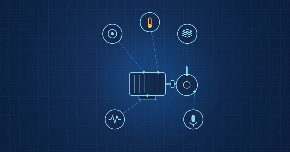
Multimodal sensing means measuring one machine through several physical channels at the same time and evaluating them together. A camera sees geometry and surface, a thermal core sees heat, a depth sensor sees distance, a microphone hears airborne sound and an accelerometer feels structure-borne vibration. None of them sees everything. Together they describe what a machine is doing far more completely than any one of them can.
This guide is written for engineers who have run vibration monitoring or machine vision before and want to know what changes when the sensors multiply. It covers definitions, the physics of each modality, fusion, timing, data volume and a practical way to start.
What multimodal sensing means in an industrial context
Multimodal sensing is the acquisition and joint evaluation of signals from sensors that measure different physical quantities on the same object. The word "modality" comes from the machine learning literature, where it describes a type of signal: image, sound, text. In a factory, a modality is better described by the physics behind it: photons in the visible or near-infrared band, long-wave infrared radiation, time of flight, pressure waves in air and acceleration of a surface.
That distinction matters. Two accelerometers on the same gearbox are a multi-sensor system, but they are still one modality. They fail in the same ways, they are blind to the same things and they are fooled by the same disturbances. A thermal camera and an accelerometer on the same bearing housing are two modalities, because a loose cable on one has nothing to do with the other.
Sensor fusion is the step that combines these signals into a single estimate or decision. Multimodal sensing is the hardware and data side; fusion is the evaluation side. You need both.
Industrial condition monitoring already has a vocabulary for this. ISO 17359 sets out general procedures for a machine condition monitoring programme, and ISO 13374-1 gives guidelines for how condition monitoring data is processed, communicated and presented. Neither standard is specific to multimodal systems, but both force the right order of thinking: failure modes first, measurements second, processing third.
The five core modalities and what each one measures
Each modality answers a different question about the machine. The table below summarises the typical industrial sensing channels and the physics they respond to. A more detailed comparison, including blind spots, is in our article on what vision, thermal, depth, sound and vibration each see and miss.
| Modality | Physical quantity | Typical industrial sensor | Typical rate | Good at |
|---|---|---|---|---|
| Vision | Reflected light, visible or near-infrared | Global-shutter CMOS camera | Tens to hundreds of frames per second | Position, presence, surface defects, motion |
| Thermal | Emitted long-wave infrared, 8 to 14 µm | Uncooled microbolometer | Below 9 frames per second on small cores such as the Lepton | Friction heat, electrical hot spots, process temperature |
| Depth | Distance via time of flight | SPAD-based direct time-of-flight sensor | Tens of frames per second | Geometry, fill level, deformation, object presence |
| Sound | Airborne pressure waves | Measurement microphone | 48 kHz for audio, a few hundred kSPS for ultrasound | Impacts, leaks, process sounds, ultrasonic friction |
| Vibration | Surface acceleration | MEMS or piezoelectric accelerometer | Several kHz to hundreds of kHz | Imbalance, misalignment, bearing and gear defects |
A few figures from real parts help calibrate expectations. The FLIR Lepton 3.5 datasheet lists 160 x 120 radiometric pixels, an 8 to 14 µm spectral range and an effective frame rate of 8.7 Hz. The ST VL53L9CX is a direct time-of-flight sensor with up to 54 x 42 zones. The ADI ADXL1002 MEMS accelerometer covers +/-50 g with a 3 dB bandwidth up to 11 kHz. These numbers already tell you that the modalities live on very different time scales.
Vision
A camera answers "where is it and what does it look like". Global-shutter sensors expose all pixels at the same moment, which avoids the skew that rolling shutters produce on fast-moving parts. Vision is excellent for geometry and surface condition but sees nothing beneath the surface and nothing about temperature.
Thermal
A radiometric thermal camera measures emitted infrared radiation and converts it into temperature. Accuracy depends on emissivity, reflected temperature and the medium in between, which is why ISO 18434-1 on thermography for condition monitoring spends so much effort on compensation. Thermal imaging is slow but sees friction, electrical resistance and process heat directly.
Depth
Direct time-of-flight sensors emit short infrared pulses and time their return. They give a coarse but robust distance map that works in poor light and on low-texture surfaces where stereo vision struggles. Depth is useful for fill levels, part presence, deformation and keeping people out of a measurement zone.
Sound and ultrasound
A microphone hears what the machine radiates into the air. Audible sound carries impacts, rubbing and process noise. Above 20 kHz, airborne ultrasound carries friction, leaks and electrical discharge with less interference from background noise. A measurement capsule and a fast converter are needed to reach that band.
Vibration
An accelerometer bolted or glued to the structure measures what travels through the metal. Vibration is the backbone of rotating machinery monitoring, with a mature standards base in the ISO 20816 series. Its weakness is that it sees only what reaches the mounting point, and it says little about heat or appearance.
Why combining modalities changes the diagnosis
The case for multimodal sensing rests on three effects: independent confirmation, separation of look-alike faults and sensor self-checking.
Independent confirmation. When two physically unrelated channels move together, the evidence is stronger than either alone. The NASA Reliability-Centered Maintenance Guide makes the same point for predictive testing in general: results from different technologies should be correlated with each other to increase the probability of detection. A rising vibration level is one data point. Rising vibration plus a warming bearing housing plus a new tonal component in the sound is a pattern.
Separation of look-alike faults. Many faults look the same in one channel. A rise in broadband vibration can mean a worn bearing, a loose foot or a process change upstream. Heat at the housing points towards friction; a camera showing a shifted base plate points towards looseness. Our article on why single-sensor monitoring misses faults walks through several of these ambiguities.
Sensor self-checking. A sensor that comes loose, saturates or loses its cable produces a signal that can look like a machine fault. When other modalities stay quiet, the system has grounds to suspect a sensor problem. Our cognitive sensors support that check by flagging their signal health and dropouts with the data.
How multimodal data is fused
Fusion is where the signals become a decision. The machine learning literature distinguishes several approaches. The survey by Baltrušaitis, Ahuja and Morency names five core challenges of multimodal learning: representation, translation, alignment, fusion and co-learning. For industrial sensing, three fusion levels cover most designs.
- Early fusion combines raw or lightly processed data before any model sees it. It can find subtle cross-modal patterns but needs well-aligned data and a lot of it.
- Feature-level fusion extracts features per modality first, for example RMS and kurtosis from vibration, peak temperature from thermal, band energy from sound, then feeds the combined feature vector to one model. This is the most common choice in practice because features are compact and interpretable.
- Late fusion runs a separate model per modality and combines the outputs with rules or a small second-stage model. It degrades gracefully when one sensor drops out and is easy to explain to a maintenance team.
There is no universally best level. Late fusion is robust and transparent; early fusion can see more but is harder to validate. Many working systems use feature-level fusion for the main decision and late-fusion rules for plausibility checks.
Time alignment, sampling rates and data volume
Fusion only works if you know which samples belong together. That sounds trivial until you look at the rates. A thermal core at 8.7 Hz delivers a frame roughly every 115 ms. A vibration channel at 200 kSPS delivers a sample every 5 µs. A camera at 100 fps sits in between. Each device usually has its own oscillator, and each oscillator runs slightly fast or slow.
A practical multimodal system therefore needs to record, for every stream, when each sample was taken and how confident that time stamp is. The general engineering problem is clock offset and drift between devices, and it is covered in depth in our article on time-stamping multimodal sensor data.
Data volume is the other surprise. As an illustrative calculation: one vibration channel at 200,000 samples per second, stored at 4 bytes per sample (a 32-bit container), produces 0.8 MB/s or about 69.1 GB per day. One 1280 x 800 monochrome camera at 100 fps produces about 102 MB/s of raw 8-bit pixels before compression. A thermal core at 160 x 120 pixels and 8.7 Hz, by contrast, produces only a few hundred kilobytes per second. Storage, compression and retention policy have to be designed together with the sensor choice, not after it.
This is also a strong argument for evaluating data close to the machine. Sending raw high-rate streams to a central server is expensive and often unnecessary when the decision can be made at the edge and only features, events and evidence clips leave the cell.
Where multimodal sensing pays off
Multimodal sensing costs more than a single sensor. It pays off where a single channel cannot reliably separate good from bad, or where false alarms are expensive. The following examples are illustrative of the application types, not reports of specific installations.
- Laser and resistance welding in battery production. A weld seam can be checked visually, its heat signature can be seen thermally and its process sound and structure-borne response can be recorded. Each carries different information about penetration and spatter.
- Rotating machinery. Pumps, fans, motors and gearboxes are the classic case for vibration, with thermal and acoustic channels adding confirmation and separating mechanical from electrical causes.
- Rail and mobile assets. Wheel flats and bearing faults show up in vibration and sound; the challenge is power and data transfer, not sensing.
- Test rigs and laboratories. Research teams often need many modalities at once and want raw data in an open format for later analysis.
For each, the question is the same: which failure modes matter, and which physical channel carries the earliest and most specific evidence of each?
How to start a multimodal sensing project
A disciplined start saves a lot of hardware. The following procedure follows the logic of ISO 17359 and adapts it to multiple modalities.
- List the failure modes and process deviations you need to see. Be specific: "outer race spall on the drive-end bearing", not "bearing problems".
- Map each failure mode to the physics it changes. Heat, geometry, distance, airborne sound, structure-borne vibration. Most faults change more than one.
- Choose the minimum set of modalities that covers every failure mode with at least one channel, and the important ones with two independent channels.
- Define bandwidth and resolution per modality. Highest frequency of interest for vibration and sound, spatial resolution and frame rate for vision, temperature range and accuracy for thermal.
- Plan mounting and installation. Accelerometer mounting method, camera field of view, thermal line of sight, microphone distance and shielding.
- Plan time-stamping, storage and export before the first recording, including file formats your data scientists can open.
- Record good and bad states with labels and context, then train and validate models on data from more than one machine or batch.
- Decide what runs at the edge and what leaves the machine: alerts, features, evidence clips or raw data.
The multimodal sensing glossary defines the terms used here if you need to align a mixed team of mechanical engineers and data scientists.
When a single sensor is enough
Multimodal is not always the answer. A single, well-placed accelerometer is still the right choice for a simple fan with one dominant failure mode and an established ISO 20816 limit. Adding modalities adds installation work, data volume and model complexity.
Use these questions as a quick check:
- Does one modality reliably separate every failure mode you care about? If yes, stay single-modal.
- Are false alarms costly enough that independent confirmation is worth the extra sensor?
- Do you need to distinguish sensor faults from machine faults without sending a technician?
- Is the process itself, not just the machine, the object of interest, as in welding or forming?
- Will the data be reused for research or model development where more channels add long-term value?
Two or more "yes" answers usually justify a multimodal set-up. Where acoustic and vibration channels overlap, decide early which one leads: a microphone hears the whole machine, an accelerometer mainly its mounting point.
How NeuroControls approaches multimodal sensing
Our platform is built around the idea that one machine should be seen, heard and felt, and that the data should be recorded and time-stamped at the machine. The Edge AI Hub runs on a RUBIK Pi 3 with a Qualcomm QCS6490, and its Multi-Camera configuration combines three OmniVision OV9281 global-shutter cameras, a FLIR Lepton 3.5 radiometric thermal core and a 48 kHz USB microphone for event recording. Vibration, acoustic and depth channels connect as separate nodes, following a one-node-per-function hub-and-node architecture.
Every stream is time-stamped on the hub, and each node's clock offset is measured continuously and written into every record, with its uncertainty. Recordings carry a versioned manifest and per-segment SHA-256 hashes and export to open formats such as NWB, MKV/HEVC, JSONL and CSV. Our engineers train custom models on customer data, from anomaly detection to severity grading.
If you want to see which combination fits your machine, the multimodal sensing solution overview and our sensing kits are good starting points.
Frequently asked questions
What is the difference between multimodal sensing and sensor fusion?
Multimodal sensing is the acquisition side: measuring one machine with sensors that respond to different physics, such as vision, thermal, depth, sound and vibration. Sensor fusion is the evaluation side: combining those signals into one estimate or decision. A multimodal system needs both. You can fuse data from identical sensors too, but that is multi-sensor fusion rather than multimodal fusion.
Which sensors are used in multimodal condition monitoring?
The most common combination for rotating machinery is an accelerometer for structure-borne vibration, a microphone for airborne sound or ultrasound and a thermal camera for heat. Process monitoring adds global-shutter cameras for geometry and surface condition, and depth sensors for distance, fill level or deformation. The right mix depends on which failure modes you need to see.
Is multimodal sensing more accurate than vibration monitoring alone?
Not automatically. A multimodal system can separate faults that look identical in one channel and can confirm a finding through independent physics, which reduces ambiguity. But accuracy depends on sensor placement, data quality, labels and validation. For a simple machine with one dominant failure mode, a well-placed accelerometer with ISO 20816 limits may be all you need.
How do you align data from sensors with different sampling rates?
Each sample or frame needs a time stamp, and the relationship between each device's clock and the reference clock must be known, including drift over time. Data is then aligned by resampling, windowing or event-based matching. The hard part is not the arithmetic but knowing how uncertain each time stamp is, so alignment errors can be bounded.
Why evaluate multimodal data at the edge instead of in the cloud?
High-rate channels produce a lot of data. One vibration channel at 200,000 samples per second already produces tens of gigabytes per day, and raw camera streams are larger. Evaluating at the machine means only results, features and short evidence clips need to travel, which reduces bandwidth, storage and latency, and keeps raw production data on site.
Sources and further reading
- ISO 17359:2018 Condition monitoring and diagnostics of machines, general guidelines
- ISO 13374-1:2003 Condition monitoring and diagnostics of machines, data processing, communication and presentation, Part 1
- ISO 18434-1:2008 Condition monitoring and diagnostics of machines, thermography, Part 1
- Teledyne FLIR Lepton 3.5 datasheet
- STMicroelectronics VL53L9CX direct time-of-flight sensor
- Analog Devices ADXL1002 MEMS accelerometer
- NASA Reliability-Centered Maintenance Guide for Facilities and Collateral Equipment (2008)
- Baltrušaitis, Ahuja, Morency: Multimodal Machine Learning, A Survey and Taxonomy