
Short answer
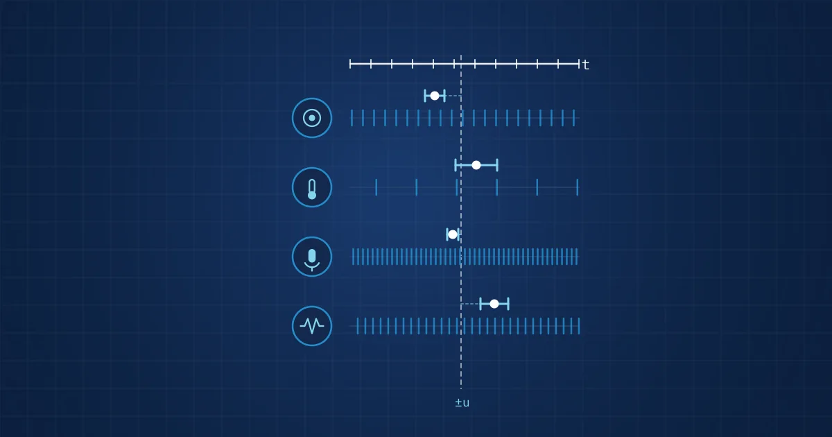
Time-stamping multimodal sensor data means recording, for every sample or frame, when it was taken and against which reference. Clock offsets matter because each sensor runs on its own oscillator, which is slightly fast or slow and drifts with temperature. Unless the offset to the reference and its uncertainty are measured and stored, data from different sensors cannot be aligned reliably afterwards.
Key takeaways
- Every device in a multimodal set-up has its own oscillator, so its clock has an offset to the reference that changes over time.
- A fractional frequency error turns directly into accumulated time error: an illustrative 20 ppm oscillator gains or loses about 1.7 seconds per day if left uncorrected.
- The four-timestamp exchange used by NTP, defined in RFC 5905, is the standard way to estimate the offset and round-trip delay between two clocks.
- Raw time stamps should never be overwritten; record the device time, the measured offset and its uncertainty, and correct during analysis.
- The Linux system clock can jump, so measurement time stamps belong on a monotonic clock with the wall-clock relationship recorded separately.
Time-stamping multimodal sensor data sounds like bookkeeping. In practice it decides whether a fused dataset means anything. A vibration burst, a thermal frame and a camera frame only tell a joint story if you know, with a stated uncertainty, how their moments of capture relate to each other.
This article covers where clock offsets come from, how big they get, how they are measured and what a recording should contain so that alignment can be done properly afterwards. It treats time as a general engineering problem first and comes to our own hub at the end.
What time-stamping multimodal sensor data involves
A time stamp is a value attached to a sample, frame or event that states when it was captured according to a particular clock. The words "according to a particular clock" carry most of the difficulty.
A few definitions help, because they are often mixed up:
- Clock offset is the difference between a device's clock and a reference clock at a given moment. RFC 5905, the NTPv4 specification, describes offset as the maximum-likelihood time offset of a server clock relative to the local system clock.
- Drift is the change of offset over time, caused by the oscillator running at a slightly wrong frequency.
- Jitter is the short-term scatter of time stamps around their ideal values. RFC 5905 defines it for NTP as the RMS average of the most recent offset differences.
- Latency is the delay between the physical event and the moment it receives a time stamp, for example while a frame sits in a driver buffer.
- Uncertainty is the honest range within which the true capture time lies.
NIST's glossary draws a useful distinction between setting clocks to the same time and setting oscillators to the same frequency, which it calls syntonisation. The NIST Time and Frequency A to Z also points out that stability says nothing about whether a frequency is right, only whether it stays the same.
Where clock offsets come from
Every camera, microcontroller, ADC and USB audio device in a multimodal rig has its own oscillator, usually a quartz crystal. No two run at exactly the same frequency.
Frequency error turns into time error
The relationship is simple. In NIST's chapter on frequency measurement, Michael Lombardi shows that the fractional frequency offset equals the accumulated time difference divided by the elapsed time. Rearranged, the time error after a period is the fractional frequency error multiplied by that period.
As an illustrative calculation, a crystal that is 20 parts per million fast gains 20 × 10⁻⁶ × 86,400 s, or about 1.7 seconds per day. At 50 ppm it is about 4.3 seconds per day. Temperature changes the frequency further, so a sensor next to a warm motor drifts differently from one in a cool cabinet.
Other sources of offset
- Start-up. A device that boots counts from zero or from whatever its real-time clock held. Its initial offset to the reference is arbitrary.
- Clock steps. When an operating system corrects its wall clock, time can jump. The Linux clock_gettime documentation notes that CLOCK_REALTIME is affected by discontinuous jumps in system time, while CLOCK_MONOTONIC is not, although it is still affected by frequency adjustments.
- Buffering latency. A frame or audio block may be time-stamped when it arrives at the host, not when it was captured. The difference depends on driver buffers, USB scheduling and system load.
- Nominal sample rates. A device that "samples at 48 kHz" from its own crystal delivers 48,000 samples per second only nominally. Counting samples gives a duration in the device's time base, not in the host's.
Why clock offsets matter for multimodal analysis
In single-sensor work, an offset of a second rarely matters. In multimodal work, the analysis depends on which samples belong together.
Consider the rate mismatch. A vibration channel at 200 kSPS produces a sample every 5 µs. A radiometric thermal core such as the FLIR Lepton 3.5 delivers frames at an effective 8.7 Hz, roughly every 115 ms. A short mechanical event lasts a fraction of a single thermal frame period. If the offset between the two streams is unknown, you cannot tell which thermal frame shows the moment of the event.
Three things break when offsets are ignored:
- Feature windows for fusion models pull data from the wrong moments, so models learn noisy or misleading cross-modal relationships.
- Causal order becomes unreliable. Did the sound come before the vibration spike, or after? For process monitoring that question can separate cause from effect.
- Labels drift away from the data they describe. An operator marks a fault on a camera image; the label is then applied to vibration data recorded at a different moment. This is one of the quieter ways a dataset is spoiled, as discussed in our article on labelling multimodal industrial datasets.
How clock offset is measured
The standard approach is to exchange time-stamped messages and estimate offset from the round trip.
The four-timestamp exchange
RFC 5905 uses four time stamps: T1 when the client sends a request, T2 when the server receives it, T3 when the server replies and T4 when the client receives the reply. The offset θ is ½ × [(T2 − T1) + (T3 − T4)] and the round-trip delay δ is (T4 − T1) − (T3 − T2). The method assumes the outgoing and return paths take equally long; any asymmetry ends up as offset error. That is why delay and its variation are a direct indicator of how far an offset estimate can be trusted.
RFC 5905 states that typical NTP clients on fast LANs are within a few hundred microseconds. That is a general statement about NTP and depends on the network, the host and how time stamps are taken.
Hardware time stamping and PTP
The IEEE 1588-2019 Precision Time Protocol uses the same principle but is designed for measurement and control systems. According to the IEEE abstract, the protocol supports accuracy and precision in the sub-microsecond range with minimal network and local computing resources, and sub-nanosecond time transfer accuracy can be achieved in a properly designed network. Much of the gain comes from taking time stamps in hardware, at the network interface, rather than in software after buffering.
Comparison of common approaches
| Approach | Where the time stamp is taken | Main error sources | Typical use |
|---|---|---|---|
| Host time on arrival | Application, when data is read | Buffering, USB scheduling, system load | Quick prototypes |
| Driver or kernel time stamp | Driver, on interrupt or transfer completion | Interrupt latency, device-internal buffering | Cameras, audio interfaces |
| Device counter plus offset estimate | Device clock, offset measured to host | Oscillator drift between estimates, path asymmetry | Distributed sensor nodes |
| PTP with hardware time stamps | Network interface hardware | Network asymmetry, oscillator quality | Distributed measurement systems |
| Shared hardware trigger | External trigger line to all devices | Trigger distribution delay, device response | Test rigs, high-speed vision |
No approach is free of error. The point is to know which errors apply and to record them.
What to record: a practical procedure
The following procedure works for most multimodal recordings, whatever the hardware.
- Pick a reference clock for the recording, usually the host's monotonic clock, and state it in the recording metadata.
- Time-stamp on a monotonic clock, not the wall clock. Record the relationship between monotonic and wall-clock time separately, so a clock step cannot corrupt measurement data.
- Keep the device's own time stamps or sample counters for every stream. Never overwrite them.
- Measure each device's offset to the reference repeatedly, not just at start-up, because drift accumulates.
- Store the offset and its uncertainty with the data, ideally per record or per segment, together with the measurement method.
- Log gaps explicitly. A dropout should leave a recorded gap, not two segments glued together as if continuous.
- Correct during analysis, not during recording. Apply offsets when building aligned datasets, so the correction can be redone if a better estimate becomes available.
- Validate with a known event, such as a tap on the machine visible in vibration, sound and video, and check that the corrected streams agree within the stated uncertainty.
When planning a new rig, add time-stamping to the sensor checklist from the start; our multimodal test rig sensor checklist includes it. Feature extraction downstream depends on it too, as covered in feature engineering for industrial signals.
How NeuroControls handles time on the hub
On our Edge AI Hub, every stream is time-stamped on the hub. For nodes connected to the hub, each node's clock offset is measured continuously and written into every record, with its uncertainty. That way an analyst knows not only when a sample was taken according to the hub, but how confident that statement is.
Recordings carry a versioned manifest, per-segment SHA-256 hashes and an append-only journal; after a power loss, the gap is logged, alerted and reported, and recording resumes by itself. A hardware sync timer is in development with LarsLabs. The recording software and the hub-and-node architecture pages describe the set-up, and our data and recording solution explains the export formats.
Frequently asked questions
What is clock offset in sensor data?
Clock offset is the difference between the time a sensor's clock reports and the time of a reference clock at the same moment. Because each device runs on its own oscillator, offsets exist from the moment devices start and change as oscillators drift. In multimodal recordings, the offset to a common reference has to be known to decide which samples from different sensors belong together.
How much does a quartz clock drift per day?
It depends on the oscillator. The accumulated time error equals the fractional frequency error multiplied by elapsed time. As an illustration, a crystal that runs 20 parts per million fast gains about 1.7 seconds per day, and one at 50 ppm about 4.3 seconds per day. Temperature changes and ageing alter the frequency further, so drift should be measured rather than assumed.
Should I use NTP or PTP for sensor data?
NTP is widely available and, according to RFC 5905, typically keeps clients on fast LANs within a few hundred microseconds. PTP, defined in IEEE 1588, is designed for measurement and control networks and supports sub-microsecond accuracy, mainly by taking time stamps in network hardware. Whichever you use, record the offset and its uncertainty with the data rather than trusting the protocol blindly.
Why should I use a monotonic clock for time stamps?
A wall clock can be stepped when the system corrects its time, which creates jumps or even backward steps in your data. On Linux, CLOCK_REALTIME is affected by such discontinuous jumps, whereas CLOCK_MONOTONIC is not. Time-stamping measurements on a monotonic clock and recording its relationship to wall-clock time separately keeps the measurement record consistent.
Should clock offsets be corrected during recording or afterwards?
Afterwards. Keep the raw device time stamps, record the measured offsets with their uncertainty, and apply the correction when building an aligned dataset. That keeps the original data intact and allows the correction to be repeated with a better offset model later. Correcting during recording bakes in an estimate that can never be checked or improved.
Sources and further reading
- RFC 5905: Network Time Protocol Version 4, Protocol and Algorithms Specification
- IEEE 1588-2019 Precision Time Protocol standard (IEEE Standards Association)
- NIST Time and Frequency from A to Z (St to Sy)
- Michael A. Lombardi, Frequency Measurement (NIST)
- Linux manual page clock_gettime(2)
- Teledyne FLIR Lepton 3.5 datasheet