
Short answer
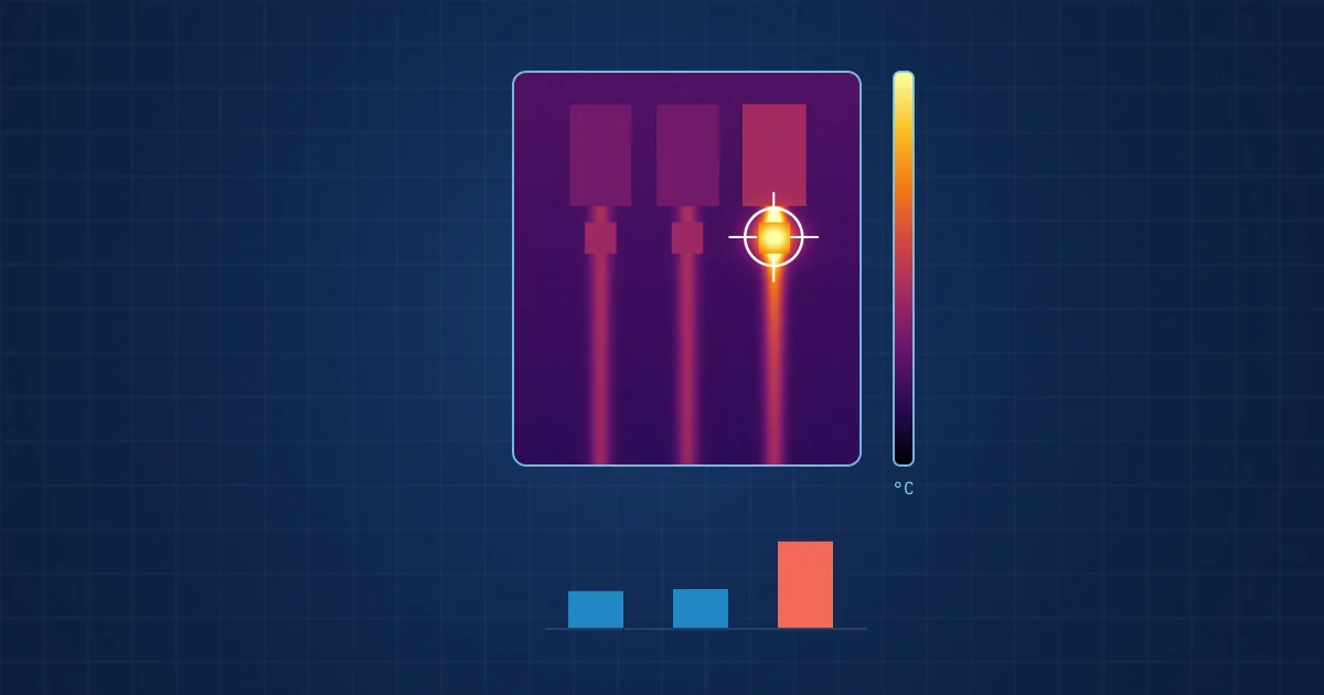
Thermal imaging for motors and electrical cabinets finds heat where it should not be: loose or corroded connections, overloaded phases, failing bearings and blocked cooling. It works when the equipment is under normal load, emissivity and reflections are handled, and the target fills enough pixels. ISO 18434-1 covers thermography for machine condition monitoring; DIN 54191 covers electrical installations.
Key takeaways
- Most electrical faults show up as a temperature difference between comparable components, so compare phase with phase rather than reading absolute temperatures.
- Bare metal reflects much of its surroundings, so a reading on a shiny busbar or terminal is often wrong unless you use a high-emissivity reference such as tape or insulation.
- Spatial resolution matters: a 160 x 120 sensor with a 57 degree field of view sees about 6 mm per pixel at one metre, so small terminals need a short distance.
- In Germany, DIN 54191 governs the inspection of electrical installations and VdS 2858 is widely cited for annual thermographic checks.
Thermal imaging for motors and electrical cabinets is one of the oldest predictive maintenance techniques and still one of the most misused. The camera produces a colourful picture whether or not the numbers in it are right. The difference between a useful survey and an expensive photo album lies in preparation: load, emissivity, reflections, distance and a reporting scheme that someone will act on.
This guide is written for maintenance and reliability engineers who already own or plan to buy an infrared camera, or who want fixed thermal sensors on critical assets. It covers what heat tells you, how to measure it properly, and where thermography needs help from other sensors.
What thermal imaging finds in motors and cabinets
Heat is the by-product of almost every electrical and mechanical fault. Resistance at a poor connection turns current into heat. Friction in a dry bearing does the same. The physics is simple; the patterns are what you learn.
| Location | Typical thermal pattern | Likely cause |
|---|---|---|
| Terminal or cable lug | Hot spot at one connection, conducting heat into the cable | Loose, corroded or undersized connection |
| Three-phase feeder | One phase uniformly warmer than the other two | Load imbalance or a high-resistance contact upstream |
| Fuse or breaker | One device warmer than identical neighbours | Internal contact wear, overload |
| Motor bearing housing | Drive end or non-drive end clearly warmer than the other | Lubrication problem, overload, misalignment |
| Motor frame | Uneven or generally high frame temperature | Blocked cooling fins, failed fan, overload, winding problem |
| Coupling | Warm coupling element | Misalignment |
| Cabinet interior | General temperature rise, warm air at the top | Failed cabinet fan, clogged filter, excessive dissipation |
A thermal image says where heat is. It rarely says why. A warm bearing housing could be a lubrication issue or simply a process load change; vibration and acoustics often settle the question.
The standards that apply
ISO 18434-1:2008, Condition monitoring and diagnostics of machines - Thermography - Part 1: General procedures, is the reference for using infrared thermography on machinery. It introduces the terminology and types of procedures, gives guidance on setting severity criteria for anomalies, covers safety, data interpretation and reporting, and describes how to determine and compensate for reflected apparent temperature, emissivity and attenuating media. ISO last reviewed and confirmed it in 2023.
DIN 54191:2017-10, Zerstörungsfreie Prüfung - Thermografische Prüfung elektrischer Anlagen, sets out how to carry out thermographic inspections of electrical installations. Its summary stresses that results reflect the installation's condition at the time of measurement, and the 2017 edition supplemented the classification criteria in section 8.2.
VdS 2858:2017-11, Thermografie in elektrischen Anlagen, is the insurers' guideline many property insurers refer to. TÜV SÜD's description of thermographic testing of electrical installations states that an annual inspection is ideal, as VdS 2858 requires, and that no more than two years should pass between inspections.
For plants with US exposure, the 2023 edition of NFPA 70B turned the former recommended practice into a standard: according to an NFPA author writing in NETA World, it converted the recommendations of the 2019 edition into requirements that an authority having jurisdiction can enforce. A TÜV SÜD summary of NFPA 70B 2023 notes thermographic inspection at least every 12 months, and at least every six months for equipment in the worst condition category.
Emissivity and reflections: the two errors that matter most
An infrared camera measures radiation, not temperature. It calculates temperature from the radiation using an emissivity value and an assumption about what the surface reflects. Get either wrong and the reading is wrong, sometimes by tens of degrees.
Emissivity is the ratio of radiation a surface emits to that of an ideal black body at the same temperature. Painted surfaces, insulation and most plastics have high emissivity and measure well. Polished copper, aluminium and stainless steel have low emissivity: they emit little and reflect a lot.
Reflected apparent temperature is the temperature of whatever the surface mirrors back at the camera: lamps, your own body, a hot neighbouring component. On a shiny busbar the reflection can dominate the reading.
Practical remedies:
- Measure on the insulation or a painted surface next to a bare connection, not on the bare metal.
- Apply high-emissivity tape or paint to fixed measurement points when you plan to trend them.
- Change your viewing angle; a reflection moves with you, a real hot spot does not.
- Measure the reflected apparent temperature and enter it in the camera; ISO 18434-1 describes procedures for determining and compensating it.
Load, safety and timing
Heat from electrical resistance scales with the square of current, so a connection that is barely warm at 20 percent load can be hot at full load. Inspect under normal operating load, record the load at the time of measurement and repeat surveys at comparable load. A survey during a night shift with half the drives idle tells you little.
Cabinet surveys usually mean opening doors on live equipment. That brings electrical safety rules, arc-flash considerations and qualified personnel into play; ISO 18434-1 includes safety recommendations for this reason. Infrared windows fitted in cabinet doors reduce the need to open them, though the window material attenuates the signal and must be compensated.
Spatial resolution: how close is close enough
Every camera has an instantaneous field of view (IFOV), the angle seen by one pixel. A target smaller than a few pixels is averaged with its background and reads too cold.
Take the FLIR Lepton 3.5 as an example. It has 160 x 120 pixels at 12 micrometre pitch, an 8 to 14 micrometre long-wave spectral range, thermal sensitivity below 50 mK and a horizontal field of view of about 57 degrees. One pixel then covers about 0.36 degrees, or roughly 6 mm at one metre. If you want at least three by three pixels on a target for a stable reading, the smallest reliable target at one metre is about 19 mm across; at 0.5 m it is about 9 mm.
The same datasheet gives radiometric accuracy as the greater of plus or minus 5 degrees Celsius or 5 percent in high-gain mode. That is fine for comparing three phases of the same feeder, where the error is common to all three. It is not fine for declaring an absolute temperature against a component rating. Handheld survey cameras are usually more accurate in absolute terms; small fixed sensors earn their place by watching continuously.
Severity criteria: how hot is too hot
There is no single international threshold. In Germany, DIN 54191 contains classification criteria in section 8.2, supplemented in the 2017 edition, and VdS 2858 is the insurers' reference. A widely quoted US scheme is Table 100.18 of the ANSI/NETA Maintenance Testing Specifications (MTS). A Fluke application note reproduces it from the 2007 edition:
| Temperature difference between similar components under similar load | Temperature difference between component and ambient air | Recommended action |
|---|---|---|
| 1 to 3 °C | 1 to 10 °C | Possible deficiency; warrants investigation |
| 4 to 15 °C | 11 to 20 °C | Probable deficiency; repair as time permits |
| No band given | 21 to 40 °C | Monitor until corrective measures can be accomplished |
| Above 15 °C | Above 40 °C | Major discrepancy; repair immediately |
Check the current MTS edition, and your insurer's scheme, before adopting these values. The same note stresses that heating is generally related to the square of the current, so the load at the time of measurement has a major impact on the temperature difference.
A field checklist for motors and cabinets
- Confirm the equipment is at normal operating load and has been for long enough to reach thermal equilibrium.
- Record ambient temperature, load current and operating state.
- Set emissivity and reflected temperature for the surface you are measuring, or measure on a high-emissivity reference.
- Work close enough that the target covers several pixels.
- Compare like with like: phase against phase, identical breakers, drive end against non-drive end.
- Capture a visible-light photo of the same view for the report.
- Classify each finding by temperature difference and component criticality, using your organisation's or your insurer's scheme, such as the criteria above.
- Re-inspect after repair to confirm the anomaly is gone.
Where continuous thermal monitoring fits
Periodic surveys catch slow-developing faults if they happen to be warm on the survey day. Intermittent faults, load-dependent hot spots and fast degradation between surveys slip through. A fixed thermal sensor on a critical motor or cabinet section turns a yearly snapshot into a trend.
Thermal data on its own also has blind spots. A bearing can be badly damaged before it gets warm, while vibration has already changed. We discuss this in why single-sensor monitoring misses faults, and the overview of what vision, thermal, depth, sound and vibration each see puts thermal in context.
How NeuroControls approaches this
Both configurations of our Edge AI Hub carry a FLIR Lepton 3.5 radiometric thermal sensor at 160 x 120. In the multi-camera configuration it sits alongside three global-shutter cameras and a microphone, so a hot spot can be viewed next to the visible image and the sound of the machine. Every stream is time-stamped on the hub and recorded on site. The hub configurations are described on the hubs page.
Each of our sensors reports its signal health and dropouts with its data, so a dropout shows up as a flagged gap rather than as a cold machine; the principle is explained on our cognitive sensors page. For plant-level use, the condition monitoring solution shows how thermal data is combined with vibration and acoustics.
Frequently asked questions
What standard covers thermal imaging of electrical cabinets in Germany?
DIN 54191:2017-10 sets out how to carry out thermographic testing of electrical installations. Many property insurers also refer to the VdS guideline VdS 2858, Thermografie in elektrischen Anlagen. For thermography applied to machines more generally, ISO 18434-1:2008 gives the general procedures, including emissivity and reflected temperature compensation, severity criteria and reporting.
How often should electrical cabinets be inspected with a thermal camera?
Annual inspection is the common reference. TÜV SÜD describes yearly thermographic inspection as ideal and in line with VdS 2858, with no more than two years between inspections. In the US, NFPA 70B 2023 calls for thermographic inspection at least every 12 months, and every six months for equipment in poor condition.
Why does my thermal camera show a shiny busbar as cold?
Polished metal has low emissivity, so it emits little infrared radiation and reflects its surroundings instead. The camera then reports a temperature closer to the reflected background than to the busbar. Measure on nearby insulation, apply high-emissivity tape or paint to a measurement point, or change the viewing angle to check whether the pattern is a reflection.
Does an electrical cabinet need to be under load for a thermal survey?
Yes. Heat at a poor connection scales with the square of the current, so a fault can be invisible at low load and obvious at full load. Inspect under normal operating load, record the load current with each image and compare surveys taken at similar load. DIN 54191 also notes that results reflect the condition at the time of measurement.
Can a low-resolution thermal sensor monitor a motor?
For trends on larger targets, yes. A 160 x 120 sensor with a 57 degree field of view covers about 6 mm per pixel at one metre, which is enough for a motor frame, bearing housing or cabinet section. Small terminals need a shorter distance. Absolute accuracy is limited, so such sensors are best used for comparisons and trends.
Sources and further reading
- ISO 18434-1:2008 Condition monitoring and diagnostics of machines - Thermography - Part 1: General procedures
- DIN 54191:2017-10 Zerstörungsfreie Prüfung - Thermografische Prüfung elektrischer Anlagen (DIN Media)
- VdS 2858:2017-11 Thermografie in elektrischen Anlagen (DIN catalogue entry)
- TÜV SÜD: Thermografische Prüfung elektrischer Anlagen
- Hannahs (NFPA), NETA World Winter 2023: NFPA 70B, developing a standard for electrical equipment maintenance
- Fluke application note: Electrical inspections using thermal imaging, with ANSI/NETA MTS-2007 Table 100.18
- TÜV SÜD: NFPA 70B 2023 new standard for electrical equipment and infrared testing
- Teledyne FLIR Lepton 3 and 3.5 datasheet