
Short answer
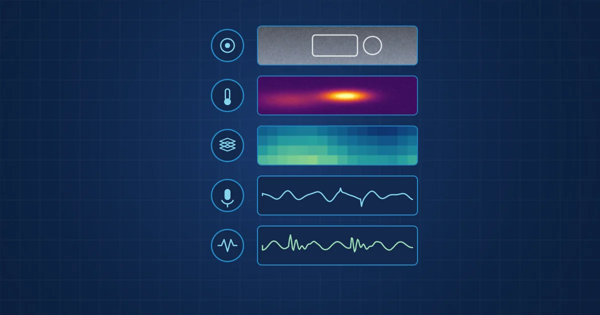
Vision sensors see geometry, position and surface defects but nothing beneath the surface. Thermal cameras see heat from friction and electrical resistance but depend on emissivity and are slow. Depth sensors measure distance robustly but coarsely. Microphones hear impacts, leaks and ultrasonic friction but pick up neighbouring machines. Accelerometers feel structure-borne faults early but only at their mounting point.
Key takeaways
- A global-shutter camera such as the OmniVision OV9281 resolves 1280 x 800 pixels at up to 120 fps but says nothing about temperature or internal condition.
- A radiometric thermal core such as the FLIR Lepton 3.5 resolves sub-50 mK temperature differences, but its absolute accuracy is specified as the greater of +/-5 °C or 5 % in high-gain mode, and it updates at 8.7 Hz.
- Direct time-of-flight sensors give a coarse depth map, 54 x 42 zones on the ST VL53L9CX, that works on low-texture surfaces and in the dark.
- Measurement microphones reach far into the ultrasonic band, while MEMS accelerometers like the ADXL1002 are limited by their 3 dB bandwidth and mounting.
- Every modality has a characteristic way of being fooled, and knowing those failure patterns is the basis for choosing a second, independent channel.
Choosing between vision, thermal, depth, sound and vibration sensors is rarely a question of which is "best". Each one responds to a different physical quantity, so each one has a characteristic set of faults it sees early, faults it sees late and faults it never sees. It also has its own way of producing convincing nonsense.
This article goes through the five modalities one by one, with figures from real industrial parts, and ends with a side-by-side table. For the bigger picture of why the modalities are combined, see our guide on what multimodal sensing is.
How to compare vision, thermal, depth, sound and vibration sensors
A fair comparison uses the same questions for every modality:
- What physical quantity does it measure? Reflected light, emitted infrared, time of flight, air pressure or surface acceleration.
- How fast and how fine? Frame rate or sample rate, spatial resolution, frequency range.
- Where does it look? Contact sensors measure one point; imaging sensors measure a field of view; microphones listen to everything in range.
- What does it miss? Faults that do not change its physical quantity.
- What fools it? Disturbances that change its quantity without any fault.
The last two questions matter most. A sensor that misses a fault costs you an unplanned stop. A sensor that is fooled costs you trust, and an alarm channel nobody trusts is soon ignored.
Vision: geometry and surface, nothing beneath
What it sees. A camera measures reflected light and gives you position, presence, dimensions, surface marks, colour (if it is a colour sensor) and motion. For moving parts, a global shutter matters: all pixels are exposed at the same instant, so a fast-moving edge is not skewed. The OmniVision OV9281, for example, is a 1 MP global-shutter sensor with 1280 x 800 pixels of 3 µm and a maximum of 120 fps at full resolution.
What it misses. Anything below the surface, anything hidden from the line of sight and anything that does not change appearance. A bearing can be well on its way to failure while looking exactly the same.
What fools it. Changing ambient light, reflections on polished metal, oil mist, dirt on the lens and parts that are slightly out of position. Near-infrared illumination and a fixed exposure help, but lens contamination remains the most common cause of slowly degrading vision results in a factory.
Thermal: heat, if you get emissivity right
What it sees. A radiometric thermal camera measures emitted long-wave infrared and converts it into temperature for every pixel. It shows friction heat in bearings and couplings, resistive heating in connections and cabinets, and process temperatures such as a weld cooling down. The FLIR Lepton 3.5 datasheet specifies 160 x 120 pixels, an 8 to 14 µm spectral band, thermal sensitivity below 50 mK and an effective frame rate of 8.7 Hz.
What it misses. Fast events. At 8.7 Hz, anything shorter than about a tenth of a second falls between frames. It also misses faults that do not generate heat yet, which for many mechanical defects is most of their early life.
What fools it. Emissivity and reflections. Bare, shiny metal emits little and reflects a lot, so a polished housing can show the temperature of the lamp across the hall rather than its own. Absolute accuracy is also limited: the Lepton 3.5 specifies the greater of +/-5 °C or 5 % in high-gain mode. ISO 18434-1 covers how to compensate for emissivity, reflected apparent temperature and attenuating media. In practice, relative measurements and temperature differences between similar components are more reliable than absolute values. Our practical guide to thermal imaging of motors and cabinets goes into this in detail.
Depth: distance without needing texture
What it sees. A direct time-of-flight (dToF) sensor emits short infrared light pulses and measures how long they take to return. The ST VL53L9CX uses 940 nm emitters and a SPAD receiver array, delivers up to 54 x 42 zones over a 55° x 42° field of view and, according to ST, measures from under 5 cm to 8.8 m. The result is a coarse but robust distance map: fill levels, part presence, deformation, gaps and people entering a zone.
What it misses. Fine detail. A 54 x 42 grid is a few thousand measurements, not a point cloud with millions of points. Small features and thin edges are averaged out within a zone.
What fools it. Very dark or very shiny surfaces, which return little light or bounce it away; strong sunlight in the infrared band; and multi-path reflections in corners. The advantage over stereo cameras is that dToF does not need surface texture, so it works on plain sheet metal and in the dark.
Sound and ultrasound: the airborne channel
What it sees. A microphone measures pressure waves in air. In the audible band, that covers impacts, rattles, rubbing, cavitation and process sounds. Above 20 kHz, airborne ultrasound carries friction, compressed-air leaks and partial discharge, with much less background from the rest of the hall. A measurement capsule such as the Microtech Gefell MK 301, a 1/4 inch condenser capsule, is specified from 5 Hz to 100 kHz in free field.
What it misses. Faults that radiate little sound, for example in heavy, well-damped housings, and anything masked by louder sources nearby.
What fools it. Neighbouring machines, forklifts, people talking, door alarms and reverberation. A microphone hears the room, not just the machine. Directional placement, short distance and the use of the ultrasonic band all help. Whether a microphone or an accelerometer is the better lead channel is the subject of our article on acoustic versus vibration monitoring.
Vibration: the structure-borne channel
What it sees. An accelerometer measures surface acceleration where it is mounted. That is where imbalance, misalignment, looseness, bearing defects and gear mesh problems first appear, often long before heat or noise. The ADI ADXL1002 is a typical industrial MEMS part: +/-50 g range, a 3 dB bandwidth up to 11 kHz, a resonant frequency of 21 kHz and 25 µg/√Hz noise density. As the ADXL1001/ADXL1002 data sheet explains, the 11 kHz point is where the response has risen by 3 dB towards the resonance; within 5 %, the response holds only up to 4.7 kHz.
What it misses. Everything that does not reach the mounting point, and everything above the usable bandwidth of the sensor and its mounting. Thermal and electrical faults may not show at all in vibration until they cause mechanical damage.
What fools it. Poor mounting, cable movement, resonances of the mounting bracket and vibration transmitted from neighbouring machines. ISO 5348 describes how the mounting method affects frequency response: a magnet on a curved surface does not give the same result as a stud on a spot face. Our explainer on bearing fault frequencies shows why bandwidth and mounting matter for early bearing detection.
Side-by-side: blind spots and what fools each sensor
| Modality | Sees early | Misses | Typically fooled by |
|---|---|---|---|
| Vision | Position errors, surface defects, missing parts, motion | Sub-surface and internal faults, temperature | Lighting changes, reflections, dirty optics |
| Thermal | Friction heat, electrical hot spots, process temperature | Fast events, faults that do not yet produce heat | Low emissivity, reflections, air movement |
| Depth | Distance, fill level, deformation, presence | Fine detail below zone size | Dark or mirror-like surfaces, strong IR light |
| Sound | Impacts, leaks, rubbing, ultrasonic friction | Quiet faults in damped housings | Background noise, reverberation |
| Vibration | Imbalance, misalignment, bearing and gear defects | Thermal and electrical faults, faults away from mount | Poor mounting, cable motion, bracket resonance |
Two patterns stand out. First, vibration and sound overlap heavily for mechanical faults, so they make a natural pair but are not fully independent. Second, the modalities that are fooled by environmental effects (vision by light, thermal by emissivity, sound by background noise) are good candidates for a confirming channel from a completely different physical domain.
Reading the table for a real machine
A useful way to use this comparison is backwards: start from a failure mode, then pick the two modalities whose "sees early" column contains it and whose "fooled by" columns share nothing. For a drive-end bearing on a pump, that is usually vibration plus thermal. For a laser weld seam, it may be vision plus sound plus thermal. For a conveyor transfer point, depth plus vision.
Treat the result as a starting point for trials, not a final design. Mounting positions, line of sight and background noise vary from site to site, and the same sensor can perform very differently on two machines of the same type.
Where NeuroControls fits
We combine these modalities in one platform so that each can cover another's blind spots. The Edge AI Hub in its Multi-Camera configuration carries three OV9281 global-shutter cameras, a Lepton 3.5 radiometric thermal core and a 48 kHz USB microphone for event recording. The Triple Eye configuration, built to order, pairs a VL53L9CX depth sensor with a global-shutter camera and a Lepton 3.5.
Vibration and acoustic channels are separate nodes: the Vibration Node uses an ADXL1002 with an 18-bit, 200 kSPS front end, and the Acoustic Node uses an MK 301 E measurement capsule with a 2 to 100 kHz capture band, production-proven from 2 to 20 kHz. The vibration front end samples far above the sensor's 11 kHz bandwidth, which leaves a wide margin for the anti-aliasing filter; the usable analysis band is still set by the sensor and its mounting. The multimodal sensing solution page shows how these combine on a machine.
Frequently asked questions
Which sensor is best for detecting bearing faults early?
Vibration is usually the earliest reliable channel for rolling-element bearing defects, because impacts from a damaged race appear at the mounting point long before the bearing runs hot. Airborne ultrasound can also pick up early friction. Thermal imaging tends to show bearing problems later, once friction is high enough to raise the housing temperature, so it works best as a confirming channel.
Can a thermal camera replace vibration monitoring?
Not for most mechanical faults. A thermal camera only shows a fault once it produces measurable heat, and small radiometric cores update at under 9 frames per second with absolute accuracy of several degrees. It is excellent for electrical connections, friction and process temperature, and as a second channel next to vibration, but it does not see imbalance or early bearing defects.
What is the difference between a global shutter and a rolling shutter camera?
A global-shutter sensor exposes all pixels at the same moment and then reads them out, so a fast-moving object is captured without geometric distortion. A rolling-shutter sensor exposes the image line by line, which skews moving edges. For conveyors, rotating parts and process monitoring, a global shutter avoids measurement errors caused by motion during readout.
Why use a time-of-flight depth sensor instead of a stereo camera?
Direct time-of-flight sensors measure distance from the travel time of light pulses, so they do not need visible texture on the surface. They work on plain sheet metal and in the dark, where stereo matching fails. The trade-off is resolution: a dToF sensor gives thousands of zones rather than a dense point cloud, which is enough for fill levels, presence and deformation.
Why does a microphone pick up so many false alarms in a factory?
A microphone measures air pressure from every source in range, not just the machine it is pointed at. Forklifts, neighbouring presses, alarms and reverberation all reach it. Short mounting distance, directional placement, ultrasonic frequency bands and models trained on site-specific background noise reduce the problem, and a second, structure-borne channel helps confirm real faults.
Sources and further reading
- OmniVision OV9281 global-shutter image sensor
- Teledyne FLIR Lepton 3.5 datasheet
- STMicroelectronics VL53L9CX direct time-of-flight sensor
- Microtech Gefell MK 301 measurement microphone capsule catalogue
- Analog Devices ADXL1002 MEMS accelerometer
- Analog Devices ADXL1001/ADXL1002 data sheet
- ISO 18434-1:2008 Condition monitoring and diagnostics of machines, thermography, general procedures
- ISO 5348:2021 Mechanical vibration and shock, mechanical mounting of accelerometers