
Short answer
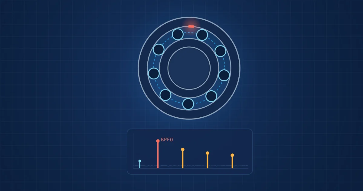
Bearing fault frequencies are the rates at which a local defect is struck as a rolling element bearing turns. BPFO is the ball pass frequency on the outer race, BPFI on the inner race, BSF is the ball spin frequency and FTF is the cage speed. Each follows from shaft speed, number of rolling elements, ball and pitch diameters and contact angle.
Key takeaways
- BPFO equals (n x fr / 2) x (1 - (d/D) x cos phi), and BPFI uses the same expression with a plus sign, so BPFO + BPFI always equals n x fr.
- A defect on a rolling element strikes both races per spin revolution, so many tables list it at twice the BSF.
- Calculated frequencies are kinematic ideals; rolling elements slide as well as roll, so measured peaks sit near, not exactly on, the calculated values.
- Early bearing damage is usually found in the envelope spectrum, not in the raw acceleration spectrum.
Bearing fault frequencies are the reason vibration analysis can say "outer race" rather than "something in the bearing". A local defect, a spall or crack on one surface, produces a small impact each time a rolling element passes over it. Those impacts repeat at a rate fixed by geometry and shaft speed. If you know the geometry, you know where to look in the spectrum.
This post gives the four formulas in plain text, works them through for a common deep groove ball bearing, and then explains why the clean numbers on paper turn into messier patterns in real data. For the spectrum basics behind it, see our introduction to vibration analysis.
The four bearing fault frequencies and their formulas
The symbols are the same in all four equations:
- fr is the shaft rotation frequency in hertz (rpm divided by 60), assuming the inner ring turns and the outer ring is fixed.
- n is the number of rolling elements.
- d is the rolling element (ball) diameter.
- D is the pitch diameter, the diameter of the circle through the ball centres.
- phi is the contact angle, zero for a deep groove ball bearing under purely radial load.
| Frequency | Name | Formula (plain text) | What it physically is |
|---|---|---|---|
| FTF | Fundamental train frequency | FTF = (fr / 2) x (1 - (d/D) x cos phi) | Rotation rate of the cage |
| BPFO | Ball pass frequency, outer race | BPFO = (n x fr / 2) x (1 - (d/D) x cos phi) | Rate at which elements pass a fixed point on the outer race |
| BPFI | Ball pass frequency, inner race | BPFI = (n x fr / 2) x (1 + (d/D) x cos phi) | Rate at which elements pass a point on the inner race |
| BSF | Ball spin frequency | BSF = (D x fr / (2 x d)) x (1 - ((d/D) x cos phi)^2) | Rotation rate of each element about its own axis |
These are the same expressions given in MathWorks' worked example on rolling element bearing fault diagnosis. Some published papers swap the signs of BPFO and BPFI or drop the factor of two in BSF, so it is worth checking any formula against a known bearing before trusting it.
Three relationships are useful sanity checks:
- BPFO = n x FTF. The outer race is stationary, so each element passes a given point once per cage revolution.
- BPFO + BPFI = n x fr. If your two calculated values do not add up to this, there is an error.
- FTF is a little under half of shaft speed. With a zero contact angle it equals 0.5 x (1 - d/D) x fr, so about 0.38 to 0.40 x fr for deep groove ball bearings with d/D between 0.2 and 0.25. It is 0.398 x fr in the example below.
A worked example: the 6205 deep groove ball bearing
The Case Western Reserve University bearing data centre publishes the geometry of the SKF 6205-2RS JEM bearing used in its test rig: ball diameter 0.3126 in (7.94 mm), pitch diameter 1.537 in (39.04 mm). A 6205 has nine balls, and as a deep groove bearing under radial load the contact angle is taken as zero.
That gives d/D = 0.2034. Working through the formulas as multiples of shaft speed:
- FTF = 0.5 x (1 - 0.2034) = 0.398 x fr
- BPFO = 4.5 x (1 - 0.2034) = 3.585 x fr
- BPFI = 4.5 x (1 + 0.2034) = 5.415 x fr
- BSF = (39.04 / (2 x 7.94)) x (1 - 0.2034^2) = 2.357 x fr
The data centre lists 0.39828, 3.5848 and 5.4152 for cage, outer ring and inner ring, which matches. For the rolling element it lists 4.7135, which is exactly twice our BSF. That is not a mistake on either side. A defect on a ball touches the inner race and the outer race once each per spin revolution, so the impact rate is 2 x BSF. Many analysis tools report this doubled value, and it is a classic source of confusion.
At an illustrative 1,800 rpm (30 Hz), the frequencies are about 12 Hz (FTF), 108 Hz (BPFO), 162 Hz (BPFI) and 71 Hz (BSF), with ball defect impacts at about 141 Hz.
Why the measured peak never sits exactly on the line
Real bearings do not behave like the kinematic model. Several effects shift or blur the pattern:
- Slip. The formulas assume pure rolling. In practice, as the review by Zhang and colleagues on bearing fault diagnostics with deep learning notes, the rolling element often undergoes a combination of rolling and sliding, so the real fault frequency deviates from the calculated one. Allow a search band of a few percent around each value.
- Load and contact angle. Axial load changes the effective contact angle, especially in angular contact bearings, and that shifts all four frequencies.
- Speed variation. A motor's speed changes with load. If you calculate from nameplate speed rather than measured speed, the error carries straight into every fault frequency.
- Wrong bearing data. Bearings get substituted during repairs. The same bore size from another manufacturer can have a different ball count.
The practical consequence: never search for a single spectral line. Search for a family of peaks with the right spacing, and confirm it with harmonics and sidebands.
Sidebands, modulation and what they tell you
The defect's location relative to the load zone shapes the signal. An outer race defect on a fixed outer ring stays in one place, often in the load zone, so it produces impacts of fairly constant strength at BPFO and its harmonics.
An inner race defect rotates with the shaft. It moves in and out of the load zone once per revolution, so its impacts are amplitude modulated at shaft speed. In the spectrum this appears as BPFI with sidebands spaced at 1 x fr. A rolling element defect rotates with the cage and is modulated at FTF, giving sidebands at cage speed around 2 x BSF.
An SKF application article on using vibration to find faulty components adds two observations from practice: initial defects can produce harmonics up to 50 times the fundamental defect frequency, and sidebands typically indicate more severe damage. Treat that as a trend indicator rather than a hard rule.
| Defect location | Main frequency family | Typical modulation | What to look for |
|---|---|---|---|
| Outer race (fixed) | BPFO and harmonics | Weak or none | Evenly spaced harmonics of BPFO |
| Inner race (rotating) | BPFI and harmonics | Shaft speed, fr | Sidebands at plus and minus fr |
| Rolling element | 2 x BSF and harmonics | Cage speed, FTF | Sidebands at plus and minus FTF |
| Cage | FTF | Often appears as sidebands on other families | Low-frequency peak below 1 x fr |
Envelope analysis: finding the impacts early
In the raw acceleration spectrum, early bearing defects are often invisible. Each impact is short and weak, and its energy is spread over a resonance band in the kilohertz range, well above the fault frequency itself. Unbalance and misalignment dominate the low-frequency end.
Envelope analysis exploits that. The procedure, in outline:
- Band-pass filter the acceleration signal around a structural resonance that the impacts excite.
- Demodulate it, typically by taking the magnitude of the analytic signal, to obtain the envelope.
- Compute the spectrum of the envelope.
- Look for peaks at BPFO, BPFI, 2 x BSF or FTF and their harmonics.
Choosing the band is the hard part. The MathWorks example uses spectral kurtosis and the kurtogram, which compute kurtosis locally within frequency bands, to find the band where the impacts stand out most. Fixed bands chosen by habit work on some machines and miss the defect entirely on others.
A short checklist before you call a bearing fault
- Confirm the bearing model and ball count, ideally from the maintenance record rather than the drawing.
- Measure actual shaft speed at the time of capture.
- Calculate all four frequencies and 2 x BSF, then check BPFO + BPFI = n x fr.
- Look for harmonic families and sidebands, not single lines.
- Compare with a baseline from the same point and operating state.
- Check that the sensor itself is healthy; a loose mount creates impacts too.
How NeuroControls approaches this
In our models, bearing fault frequencies are inputs, not answers. Our engineers derive features around the calculated families, such as envelope energy in a band around BPFO and its harmonics, normalised by speed, and combine them with broadband and time-domain features. A model trained on customer data then grades whether a pattern is present and how severe it is. We explain how those features are built in our post on feature engineering for industrial signals.
The Vibration Node records a single channel at 18 bits and 200 kSPS, which leaves room for the kilohertz-range resonances that envelope analysis needs. The node flags its signal health and dropouts with every segment; whether a mount has come loose still has to be checked on the machine, as in the checklist above. For bearings where mounting an accelerometer is awkward, acoustic monitoring can carry some of the same information; more on our approach is on the condition monitoring page.
Frequently asked questions
What is the formula for BPFO?
BPFO, the ball pass frequency of the outer race, equals (n x fr / 2) x (1 - (d/D) x cos phi). Here n is the number of rolling elements, fr the shaft speed in hertz, d the ball diameter, D the pitch diameter and phi the contact angle. For most deep groove ball bearings BPFO lands between about three and five times shaft speed.
Why is BPFI higher than BPFO?
The inner race rotates with the shaft while the rolling elements move in the same direction more slowly, at cage speed. The relative speed between elements and inner race is therefore higher than between elements and the stationary outer race. That is why BPFI uses a plus sign in the formula, and why BPFO plus BPFI always adds up to the number of elements times shaft speed.
Why do some tables give the ball defect frequency as twice BSF?
BSF is the rate at which a ball rotates about its own axis. A defect on that ball contacts the inner race and then the outer race during each spin revolution, so it produces two impacts per revolution. Tables that list a rolling element defect frequency, such as the Case Western Reserve data, usually give this doubled value. Check which convention your software uses.
Why does the measured bearing fault frequency differ from the calculated one?
The formulas assume pure rolling, constant speed and a known contact angle. In real bearings the elements partly slide, load changes the contact angle and motor speed varies with load. Bearing substitutions can also change the geometry. Search a band of a few percent around each calculated value and confirm with harmonics and sidebands.
Do I need envelope analysis to detect bearing faults?
For early defects, usually yes. The impacts from a small spall are weak and excite high-frequency resonances, so they barely show in a raw spectrum dominated by running-speed components. Band-pass filtering around a resonance, demodulating and taking the spectrum of the envelope exposes the repetition rate of the impacts at the bearing fault frequencies.