
Short answer
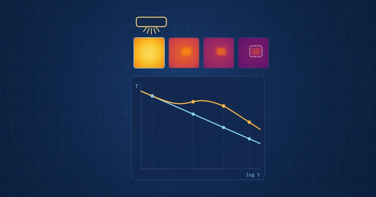
Infrared impulse thermography detects sub-surface defects by heating a surface with a short pulse of light and recording how it cools with an infrared camera. Voids, delaminations and poor bonds slow the flow of heat into the part, so the surface above them stays warmer for longer. The time at which a defect appears grows roughly with the square of its depth.
Key takeaways
- Impulse thermography is an active method: an external heat pulse from flash lamps, LEDs or a laser creates the thermal contrast that passive thermography lacks.
- Published studies report that characteristic contrast times are approximately proportional to the square of defect depth, so a defect twice as deep appears about four times later.
- Small and deep defects produce weak contrast because heat flows around them, which sets practical limits on what the method can find.
- At European level, EN 17119:2018 covers active thermography; in Germany, DIN 54184:2017-10 describes pulse thermography with optical excitation, and DIN EN 16714-1 sets out the general principles of thermographic testing.
Infrared impulse thermography is one of the simplest ideas in non-destructive testing. Heat a surface for an instant, watch it cool, and look for places where it cools differently. A void or delamination under the surface acts as a thermal barrier, and the patch of surface above it stays warm a little longer than its surroundings. An infrared camera sees that difference without touching the part.
The method is fast, contact-free and works on a whole area at once. It also has firm physical limits on depth and defect size. This article explains how it works, what controls those limits, and why we investigated it in the MYW.AI 4 QM research project on medical ultrasound probes. If you are new to thermal imaging, our practical guide to thermal imaging covers the passive basics first.
Passive and active thermography
Passive thermography measures heat that is already there: a hot bearing, an overloaded connection. It works when the fault itself generates heat.
Active thermography introduces heat on purpose and observes the response. That makes defects visible that produce no heat of their own, such as a void in an adhesive layer or a crack under a coating. Impulse thermography, also called pulse or flash thermography, is the active variant with a short, intense heating pulse. Others use modulated (lock-in) or step heating, and some use ultrasound or induction instead of light as the heat source.
The general principles of thermographic testing are set out in DIN EN 16714-1:2016, the German version of EN 16714-1. At European level, EN 17119:2018, Non-destructive testing - Thermographic testing - Active thermography, defines procedures for testing with active thermography, covering data acquisition and analysis, with informative guidance on choosing an excitation source and no acceptance criteria. In Germany, pulse thermography with optical excitation is described in DIN 54184:2017-10, Impulsthermografie mit optischer Anregung. Its summary names flash lamps or sufficiently powerful LED or laser sources for heating, notes that longer pulses may be used for materials with low thermal diffusivity, and lists detecting defects, measuring layer thickness and determining thermal material properties among its uses.
How infrared impulse thermography works, step by step
- Pulse. A flash lamp, LED array or laser deposits a short burst of energy on the surface and briefly raises its temperature.
- Diffusion. Heat flows from the surface into the material. In sound material it spreads evenly and the surface cools along a smooth, predictable curve.
- Obstruction. Where a void, delamination or disbond lies below the surface, heat flow is blocked. The surface above it cools more slowly.
- Recording. An infrared camera records the surface at a high frame rate from just before the pulse until the contrast has faded.
- Analysis. Software compares each pixel's cooling curve with a reference, either a known sound area or a model, and maps where and when contrast appears.
The result is not a single image but a sequence. Shallow defects appear early and fade early; deeper defects appear later and more faintly.
Depth, time and contrast
The relationship between depth and time follows from heat diffusion. Zhao, Mehnen, Sirikham and Roy, in a 2017 paper on defect depth measurement in pulsed thermography (Mechanical Systems and Signal Processing), report that the peak contrast time and the peak slope time are each approximately proportional to the square of the defect depth. Sirikham, Zhao and Mehnen make the same observation in their Infrared Physics and Technology paper on thermal wave reflection coefficients.
The square law has practical consequences:
- Record length scales with depth squared. From heat diffusion, the characteristic time is of the order of z squared divided by the thermal diffusivity alpha, where z is the defect depth. For a given material, the record length therefore scales with the square of the deepest depth of interest.
- Twice as deep means about four times later. If a defect at one depth peaks at a given time, one at double that depth peaks at roughly four times that time, and with lower contrast.
- Thermal diffusivity sets the timescale. Metals conduct heat quickly, so the informative part of the cooling curve is short; polymers and composites are slow, so it stretches out. The camera's frame rate and recording length must match.
- Lateral size matters. Zhao and colleagues note that the smaller the defect, the lower the maximum contrast, because heat flows around it in three dimensions. Accuracy of depth estimates falls for small defects for the same reason.
In frequency-domain processing, the same physics appears differently: the authors note that deeper defects are visible at lower frequencies and shallower defects at higher ones.
What the camera has to deliver
Two camera properties limit what you can find.
Frame rate. Early-time behaviour carries the information about shallow defects. A NASA Langley study by Plotnikov and Winfree on temporal treatment of thermal responses for depth estimation points out that characterising this early period requires a sampling rate high enough to capture it. Our own reasoning from the square law adds a consequence: because characteristic times scale with depth squared divided by thermal diffusivity, thin layers of highly conductive material cool very quickly, which calls for a fast cooled or high-speed camera. A low-cost microbolometer running below 9 Hz, which is fine for monitoring motors, cannot resolve such fast transients, though it can follow slow ones in low-diffusivity materials.
Thermal sensitivity. Deep and small defects produce contrasts of a fraction of a kelvin. Noise-equivalent temperature difference, together with averaging and good reference subtraction, decides whether that contrast is visible at all.
Where impulse thermography fits among NDT methods
| Method | Contact needed | Area per shot | Strengths | Limits |
|---|---|---|---|---|
| Impulse thermography | No | Whole field of view | Fast, contact-free, good for near-surface delaminations and disbonds | Depth limited; small deep defects give weak contrast; emissivity and surface finish matter |
| Ultrasonic testing | Usually, via couplant or immersion | Point or line, scanned | Deeper penetration, precise depth | Coupling required; slower area coverage |
| X-ray or CT | No | Whole part, CT slow | Volumetric, sees voids of many kinds | Equipment cost, radiation protection, contrast for thin planar gaps |
| Visual inspection | No | Whole field | Cheap, fast | Surface only |
Impulse thermography is strongest where defects are planar, close to the surface and parallel to it: delaminations, disbonds, voids in adhesive joints. Those are exactly the defects that matter in layered assemblies.
Medical ultrasound probes: the MYW.AI 4 QM context
A medical ultrasound probe is a layered assembly. As Zhang, Chen and Yang describe in a 2025 paper on ultrasound linear array transducer design, a typical stack has a piezoelectric active layer, matching layers between the elements and the lens, a backing layer to absorb rearward sound, and an acoustic lens. The layers are bonded, and their acoustic performance depends on those bonds being uniform and free of voids.
That makes probes a natural candidate for impulse thermography in quality management. A disbond or void under the lens or in a matching layer is a planar, near-surface defect, the kind the method sees best. It is invisible from outside and expensive to find once the probe is in service.
The MYW.AI 4 QM research project combines infrared impulse thermography with neuromorphic pattern matching to detect such sub-surface defects in medical ultrasound probes. The idea behind the second half: instead of processing every frame of a long thermal sequence in full, an event-driven, neuromorphic approach responds to where and when the cooling pattern departs from the expected one, and matches that spatio-temporal signature against learned patterns. Our article on neuromorphic computing for condition monitoring explains the computing principles. This is quality inspection of a manufactured component; it involves no patient data and makes no clinical claims.
Practical checklist for an impulse thermography test
- Know the expected defect depth range and the material's thermal diffusivity, and size frame rate and record length to match.
- Control surface emissivity; shiny or uneven surfaces may need a removable coating.
- Use reference samples with known artificial defects at relevant depths and sizes.
- Record a pre-pulse frame for every shot and subtract it.
- Check heating uniformity across the field of view, because uneven heating mimics defects.
- Validate any automated classifier on parts that were not used to develop it, to avoid the shortcut learning we describe in validating industrial AI models.
How NeuroControls approaches this
MYW.AI 4 QM is listed with our other work on the research projects page, and the neuromorphic side is described on our neuromorphic technology page. Thermal sensing in our current products uses a FLIR Lepton 3.5 radiometric sensor for monitoring tasks; impulse thermography needs a different camera and excitation, so applications like this are project work rather than an off-the-shelf kit.
If you have a layered component where hidden bonding defects matter, our custom systems page explains how we scope such projects, and from research rig to product describes how we take a method from a laboratory set-up to an inline system. For medical technology manufacturers, the medical technology page gives more context.
Frequently asked questions
What is infrared impulse thermography?
Infrared impulse thermography, also called pulse or flash thermography, is an active non-destructive testing method. A short pulse from flash lamps, LEDs or a laser heats the surface, and an infrared camera records how it cools. Sub-surface voids, delaminations and disbonds block heat flow, so the surface above them stays warmer for longer and appears as a contrast in the image sequence.
How deep can pulse thermography detect defects?
There is no single figure, because detectable depth depends on the material's thermal diffusivity, the defect's lateral size and the camera's sensitivity. Contrast times scale roughly with the square of depth while contrast weakens, so deep, small defects fade into noise. The method is strongest for near-surface, planar defects such as delaminations and disbonds that are wide compared with their depth.
Which standard covers impulse thermography in Germany?
DIN 54184:2017-10, Zerstörungsfreie Prüfung - Impulsthermografie mit optischer Anregung, describes pulse thermography with optical excitation from flash lamps, LEDs or lasers. General principles of thermographic testing are in DIN EN 16714-1:2016, the German version of EN 16714-1. Both are current in DIN's catalogue. At European level, EN 17119:2018 defines procedures for active thermography in general.
What is the difference between passive and active thermography?
Passive thermography measures heat that the object produces itself, such as a hot bearing or a loose electrical connection. Active thermography adds heat from outside, with a light pulse, modulated lamps, induction or ultrasound, and observes the thermal response. Active methods reveal defects that produce no heat, such as voids in bonded joints or cracks under coatings.
Why use impulse thermography on medical ultrasound probes?
A probe is a bonded stack of piezoelectric elements, matching layers, backing and lens. Voids or disbonds between these layers are planar, near-surface defects that are invisible from outside, and thermography detects that kind of defect well and without contact. The MYW.AI 4 QM research project investigates this for quality management, combined with neuromorphic pattern matching.
Sources and further reading
- DIN 54184:2017-10 Non-destructive testing - Pulse thermography using optical excitation
- EN 17119:2018 Non-destructive testing - Thermographic testing - Active thermography (EVS catalogue entry)
- DIN EN 16714-1:2016-11 Non-destructive testing - Thermographic testing - Part 1: General principles
- Zhao, Mehnen, Sirikham, Roy: A novel defect depth measurement method based on Nonlinear System Identification for pulsed thermographic inspection, MSSP 2017, doi 10.1016/j.ymssp.2016.08.033
- Sirikham, Zhao, Mehnen: Determination of thermal wave reflection coefficient to better estimate defect depth using pulsed thermography, Infrared Physics and Technology 2017
- Plotnikov and Winfree: Temporal Treatment of a Thermal Response for Defect Depth Estimation, NASA Langley
- Zhang, Chen, Yang: Design and fabrication of ultrasound linear array transducer used in ultrasound endoscope (arXiv:2507.18628)