

Short answer
Resistance spot welding of battery tabs fails in two classic ways: cold welds, where too little heat forms a weak or unbonded joint, and expulsion, where too much heat ejects molten metal. Both follow from deviations in current, time, force and contact conditions. Electrical signals, electrode force and displacement, and vibro-acoustic response at the weld head can monitor every weld inline; resistance tests after welding alone cannot.
Key takeaways
- Cold welds on battery tabs come from too little heat at the interface, for example from short weld times, excessive electrode force that spreads the current, or worn electrodes.
- Expulsion is the ejection of molten metal particles, as defined in ISO 17677-1, and on battery cells it also brings electrode erosion and burn marks that can later corrode.
- A study on 18650 cells found minimal differences in electrical resistance between welds, so mechanical strength had to decide weld quality; resistance testing alone is not enough.
- In the e-WAS feasibility study, a sensor integrated in the weld head recorded the vibro-acoustic response at 64 kSPS, and the damping after a successful weld was clearly measurable and scaled with weld current.
Resistance spot welding of battery tabs is still common wherever cylindrical cells are connected with nickel or nickel-plated steel strips: e-bike and LMT packs, power tools, many stationary storage modules. It is cheap, fast and well understood. It also fails quietly, because a bad spot weld often looks like a good one.
This post explains the two failure modes that matter most, cold welds and expulsion, and compares the ways to monitor each weld while it is being made.
How resistance spot welding joins battery tabs
Resistance welding generates heat by passing a high current through the contact between two parts. The heat is highest where the resistance is highest, ideally at the interface between tab and cell terminal, which melts locally and forms a nugget.
On battery cells, both electrodes usually sit on the same side, on top of the tab, because the cell itself cannot be clamped from below. This arrangement is called series or parallel gap welding. Current flows from one electrode down through the tab into the cell can and back up through the second electrode. Masomtob and colleagues studied exactly this set-up on 18650 cells with Hilumin (nickel-plated steel) connectors, comparing it with pure nickel in simulation.
According to the joining review by Das et al., resistance spot welding is used for tab materials up to about 0.4 mm thick, including steel, nickel, copper and aluminium. The authors note that aluminium and copper are hard to weld this way because of their high electrical and thermal conductivity, with aluminium's oxide layer as an added difficulty. They also list electrode sticking as a known problem. Projections on the tabs can improve joint quality and make welding easier.
Cold welds: too little heat in the right place
A cold weld is a joint where the interface did not reach melting temperature over a sufficient area. The parts may stick together, sometimes well enough to survive handling, but the bond is weak or absent.
Masomtob et al. describe several routes to a cold weld on battery cells:
- Weld time too short. Not enough heat is produced, and the result is a weak or unbonded contact.
- Electrode force too high. The tab deforms, the contact area grows, and the current spreads over many paths instead of a small spot. The temperature never reaches the melting point.
- Position on the cell. Near the centre of the terminal, the can supports the tab less, deformation is higher and the same mechanism applies.
Electrode wear, surface contamination and oxide layers add to this list in production. All of them lower the current density at the interface, which is why cold welds tend to drift in slowly over a shift rather than appearing suddenly.
Expulsion: when the heat finds a way out
ISO 17677-1, the vocabulary standard for resistance spot, projection and seam welding, defines expulsion as the ejection of molten metal particles (as cited by Antal et al.). It can occur at the interface between the parts or at the contact between electrode and sheet. In a 2024 paper on expulsion quantification by Antal, Razza and De Maddis, the authors point out that expulsion at the faying surface is the more harmful variant, because liquid metal leaves the nugget. They link expulsion to high current, initial gaps and welds close to an edge.
On battery cells, expulsion has its own consequences. Masomtob et al. saw welding splashes when the supply voltage was set too high, with rapid erosion of the electrode tips as a result. Too much heat also left burn marks around the weld spots, which they warn can develop into rust in humid conditions. Too little force has a similar effect from the other side: a weak contact can produce a small arc and metal sparking.
The table summarises the parameter deviations and what they produce.
| Deviation | Typical result | Visible after welding? |
|---|---|---|
| Weld time too short | Weak or unbonded joint (cold weld) | Often not |
| Weld time too long | Burn marks, electrode wear | Yes, discolouration |
| Force too low | Arcing, sparking, metal splash | Sometimes |
| Force too high | Excessive deformation, dispersed current, weak joint | Deformation only |
| Voltage or current too high | Expulsion, electrode erosion, burn marks | Usually |
| Worn or contaminated electrodes | Drift towards cold welds or sticking | Rarely |
Why a resistance test does not settle the question
Most module lines measure electrical resistance after welding. It is fast and catches missing welds. But on its own it is not a reliable judge of joint strength.
In the 18650 study, the resistance differences between weld contacts were minimal, so the authors used mechanical strength as the deciding criterion and defined good parameter windows as those that withstood more than 200 N in shear. A separate study on quality analysis of welds from an automatic battery pack spot welder compared test methods and also settled on a destructive breakage test.
Destructive tests, however, can only be done on samples. The gap between "resistance looks fine" and "joint is mechanically sound" is exactly where inline monitoring earns its place. The same issue appears in laser welding, as discussed in laser welding of battery cells: defects and inline inspection.
Monitoring signals compared
Every spot weld produces signals that can be recorded at the machine. They differ in what they reveal and how hard they are to install.
| Signal | What it captures | Strengths | Limitations |
|---|---|---|---|
| Weld current and voltage | Energy delivered | Often available from the power supply | Says little about contact conditions on its own |
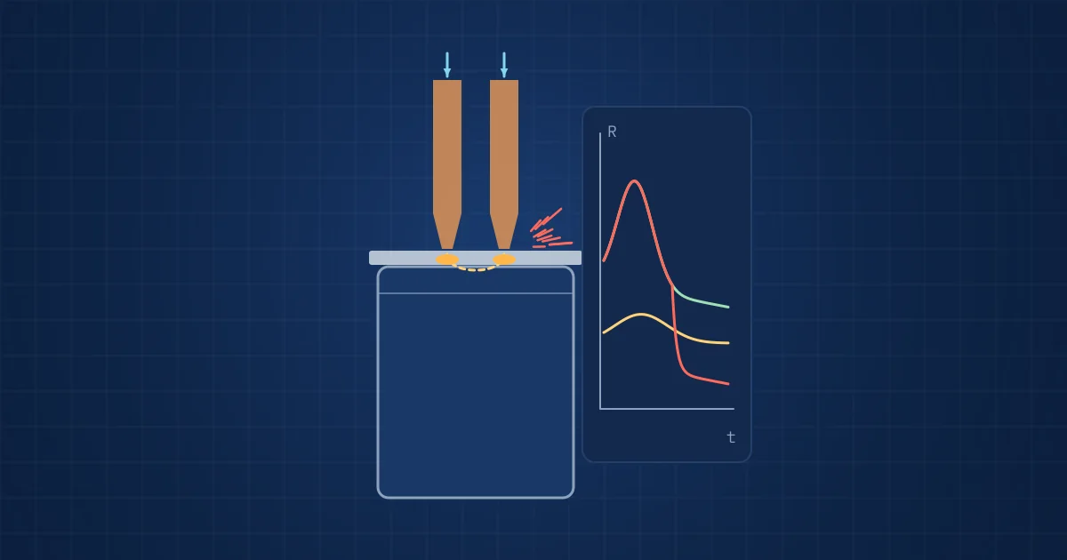
| Dynamic resistance | Change of resistance during the weld | Shows a sudden decline at expulsion (Antal et al.) | Needs voltage taps close to the electrodes |
| Electrode force and displacement | Thermal expansion, collapse, indentation | Sensitive to nugget growth and expulsion | Requires sensors in the weld head |
| Vibro-acoustic response | How the joint and cell structure ring and decay | Directly linked to mechanical coupling | Needs careful sensor mounting and training data |
| Post-weld vision | Burn marks, splashes, position | Simple, documents every weld | Cannot see interface bonding |
Antal et al. built their expulsion index from electrode force and displacement, sampled at 40 kHz, and suggest that the index trend could reflect electrode wear and warn the operator before expulsion occurs. That is the kind of early drift signal production engineers want.
What e-WAS showed about vibro-acoustic weld monitoring
In 2021 we carried out e-WAS, a feasibility study funded through Germany's ZIM programme, with VRI, LarsLabs and PORON. The idea was to integrate a sensor into the weld head and record the vibro-acoustic response of each spot weld at 64 kSPS.
The key observation was simple. After a successful weld, the damping of the response was clearly measurable, and it scaled with weld current. Our reading of the physics is that a tab that has fused to the cell terminal couples mechanically to the much larger mass of the cell, so the structure rings down differently than a tab that is only pressed on. That is precisely the property a resistance measurement cannot see.
If you want to understand the signal side, our posts on vibration analysis from time signal to spectrum and on when a microphone beats an accelerometer explain the basics.
A practical set-up checklist
Before adding monitoring to a spot welding cell, check the following:
- Is weld current and voltage logged per weld, with the cell and position identifier?
- Can force and displacement be measured in the weld head, or does the machine already provide them?
- Is there a mounting point for a vibro-acoustic sensor close to the weld, mechanically stable and away from cable strain?
- Do you have a destructive test plan (peel or shear) to label a training set of good and bad welds?
- Are electrode dressing and replacement events recorded, so that drift can be separated from tool changes?
- Will results be stored per weld, so that a returned pack can be traced back joint by joint?
Where NeuroControls fits
Our Process Monitoring Kit is built on the measurement chain from e-WAS and the later e-LAS+ laser welding project. It combines the Edge AI Hub with an Acoustic Node and a Vision Node, with an optional Vibration Node, and is built to order. Models are trained by our engineers on the customer's own weld data and delivered as ONNX. Weld current and voltage can be taken from the welding controller on request. A model trained this way grades and reports each weld; it never sits in the weld control loop. See the kits overview and our battery production page for details, or the research projects page for the background.
Frequently asked questions
What is a cold weld in battery tab spot welding?
A cold weld is a joint where the interface between tab and cell terminal did not melt over a sufficient area, so the bond is weak or absent. Typical causes are a weld time that is too short, excessive electrode force that spreads the current, worn or contaminated electrodes, and welding near the centre of the terminal where the tab deforms more.
What causes expulsion in resistance spot welding?
Expulsion is the ejection of molten metal, defined in ISO 17677-1. It is driven by too much heat input, for example from excessive current or voltage, and by disturbances such as gaps and welds close to an edge. On battery cells it also erodes electrode tips and can leave burn marks that may later corrode in humid conditions.
Can a resistance measurement detect a bad spot weld on a battery cell?
It detects missing or grossly defective welds, but on its own it does not reliably separate strong from weak joints. A study on 18650 cells with nickel-plated steel (Hilumin) connectors found minimal resistance differences between welds and used shear strength above 200 N as the quality criterion instead. Inline monitoring of each weld closes this gap.
Which signals are used to monitor resistance spot welds inline?
Common signals are weld current and voltage, dynamic resistance during the weld, electrode force and displacement, vibro-acoustic response measured at the weld head, and post-weld images. Dynamic resistance and force signals are sensitive to expulsion, while vibro-acoustic damping reflects how well the tab has coupled mechanically to the cell.
Why are copper and aluminium tabs hard to resistance weld?
Copper and aluminium conduct electricity and heat very well, so little heat is generated at the interface and it dissipates quickly. Aluminium also carries an oxide layer. For these materials, ultrasonic or laser welding is often preferred, while resistance welding works well on nickel and nickel-plated steel tabs up to about 0.4 mm thick.
Sources and further reading
- Masomtob et al. (2017): Parametric study of spot welding between Li-ion battery cells and sheet metal connectors, Engineering Journal 21(7)
- Das, Li, Williams, Greenwood (2018): Joining technologies for automotive battery systems manufacturing, World Electric Vehicle Journal 9(2) 22
- Antal, Razza, De Maddis (2024): Frequency domain signal analysis based index for expulsion quantification in resistance spot welding
- ISO 17677-1:2021 Resistance welding, vocabulary, part 1: spot, projection and seam welding
- Racewicz, Fijałkowski (2023): Quality analysis of welds made with an automatic battery pack spot welding machine, Elektronika ir Elektrotechnika 29(3)