
Short answer
Laser welding of battery cells typically fails through lack of fusion or lack of connection caused by gaps, excessive penetration that pierces the cell can, porosity, and brittle intermetallic phases in copper-aluminium joints. Inline inspection combines pre-process gap measurement, in-process sensing (photodiodes, cameras, optical coherence tomography, acoustics) and post-process surface and resistance checks, because no single sensor sees every defect.
Key takeaways
- The most consequential laser weld defects in battery cell connections are lack of fusion, lack of connection across a gap, excessive penetration into the cell can, porosity and brittle Al-Cu intermetallic layers.
- Part-to-part gap is a dominant cause of poor connections: in one 2025 study on aluminium busbar welds, the measured sound power showed a relatively strong negative correlation with the gap (Pearson coefficient -0.797).
- Cameras see the surface well but not the penetration depth, while optical coherence tomography measures depth directly but needs recalibration when process parameters change.
- Resistance checks after welding are standard practice and do carry information on joint strength, but the differences between joints can be small, so they need a precise measurement and should not be the only quality gate.
Laser welding of battery cells is the standard way to connect cylindrical, prismatic and pouch cells to busbars in many module designs. It is fast, contact-free and precise. It is also unforgiving: the materials are thin, often dissimilar, highly reflective, and sit millimetres above a live electrochemical cell.
This post lists the defects that matter in practice, explains their causes, and compares the inline inspection methods that can catch them. It is written for process and quality engineers setting up or improving a welding station in module assembly.
Where laser welding is used in cell and module production
The joining technology review by Das, Li, Williams and Greenwood (World Electric Vehicle Journal, 2018) covers the joining methods used in battery systems, including resistance, ultrasonic and laser welding. They rate laser welding as mature (manufacturing readiness level 10) for prismatic case sealing and module joining, and at levels 4 to 6 for cylindrical and pouch module joining at the time of writing.
Typical laser welding positions in a module line are:
- cell terminal to busbar or connector plate, for cylindrical and prismatic cells
- tab to busbar, for pouch cells
- case and lid sealing of prismatic cells, at cell level
- sense wire and cell contacting system connections
The VDMA and PEM RWTH Aachen description of module assembly lists laser powers of 1,000 to 4,000 W for cell contacting, and stresses two process requirements: low heat input into the cell, and joint surfaces free of dust and grease with low reflection.
The defects that matter, and what causes them
Battery joints differ from structural welds. The joint has to carry current with low resistance for the life of the pack, survive vibration and thermal cycling, and must never damage the cell underneath. That shifts the priority list of defects.
| Defect | Typical cause | Consequence in the battery |
|---|---|---|
| Lack of fusion | Too little energy, poor coupling on reflective surfaces, defocus | Upper part barely melted; no load-bearing joint |
| Lack of connection | Part-to-part gap too large for the melt to bridge | Weld looks present on top but does not join the parts |
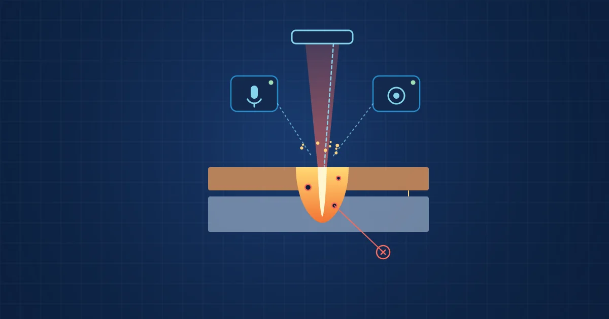
| Excessive penetration (piercing) | Too much energy, thin can wall, focus drift | Cell can punctured, risk of electrolyte leakage and thermal runaway |
| Porosity | Unstable keyhole, contamination, overheating of low-melting aluminium | Reduced cross-section, crack initiation, higher resistance |
| Brittle intermetallic layers | Excessive mixing of copper and aluminium (or nickel and aluminium) | Low ductility, cracks under cyclic load |
| Spatter | Keyhole instability, contamination | Conductive particles inside the module, reduced seam volume |
Gap and lack of connection
A 2025 study by Basile and colleagues at Politecnico di Torino on remote laser welding of 1 mm aluminium 1050 busbar-to-terminal joints shows how narrow the window is. At 850 W and below they saw lack of fusion, with only surface marking on the upper sheet. Between 900 and 1,000 W the upper sheet melted, but even at zero gap the joint did not connect properly to the lower sheet. Only from 1,050 to 1,350 W did they get sound connections, and at 2,000 W the beam pierced through. They classed a joint as connected when its effective depth exceeded 25 % of the sheet thickness.
The authors also point out the safety stake directly: an undetected keyhole that passes through the terminal can puncture the cell, with possible electrolyte leakage and thermal runaway as consequences.
Dissimilar metals and intermetallics
Copper and aluminium joints form intermetallic phases when the two metals mix in the melt. In a study of green laser overlap welding of copper to aluminium battery tabs, Kaufmann et al. list phases from Al2Cu to Al4Cu9 and found maximum shear strength with low intermixing and without large, complex intermetallic structures. Pores appeared when they went above the reference line energy.
The same paper found the electrical resistance relatively stable across process parameters: all joints measured between the resistances of the two base materials, and the values of all parameter sets differed by less than 13 %. It also found that resistance and tensile strength were correlated, with the lowest resistances measured for the highest tensile loads, and suggests that a non-destructive resistance measurement may allow joint strength to be predicted. Resistance is therefore a useful signal, but because the differences are small it needs a precise measurement, and on its own it does not show the intermetallic structure of the joint.
Why the usual weld standards only partly help
ISO 13919-2:2021 sets quality levels for imperfections in electron and laser beam welds in aluminium, magnesium and pure copper. It applies to material 0.5 mm thick or greater and addresses visual examination, not metallurgical aspects. Many battery connectors and tabs are thinner than that, and the defects that matter most here (penetration into the can, intermetallics) are not visible from the surface. Most cell manufacturers and integrators therefore define their own acceptance criteria based on cross-sections, peel or shear tests and resistance.
Inline inspection methods compared
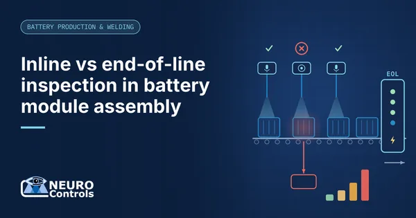
Inline inspection means checking every joint during or immediately after welding, at line speed, as opposed to sampling joints for destructive tests. The methods fall into three stages.
| Method | Stage | What it sees well | Main limitations |
|---|---|---|---|
| Camera or laser line gap measurement | Before welding | Gap, position, presence of parts | Cannot see the weld itself |
| Photodiodes (process light, back reflection) | During | Changes in coupling and process emission, fast and cheap | Indirect; less sensitive to some parameter changes |
| Coaxial or high-speed camera | During | Melt pool and surface behaviour, spatter | Subsurface features such as penetration depth remain hard |
| Optical coherence tomography (OCT) | During | Keyhole depth, measured directly | Needs recalibration when process parameters change |
| Acoustic (airborne microphone or structure-borne sensor) | During | Keyhole stability, energy input, gap effects | Background noise; requires training data per joint type |
| Seam surface vision or 3D profile | After | Seam width, position, surface pores, spatter | Surface only |
| Electrical resistance | After | Gross failures, missing joints; correlates with joint strength | Differences between joints can be small, so it needs a precise measurement |
| X-ray or ultrasound | After, usually sampled | Internal pores, connection area | Slow and costly for 100 % inspection |
The comparison of in-process sensors draws on the literature review in Basile et al., who note that camera-based and laser-based sensors are well established for surface features while "direct measurement of subsurface features remains an unsolved problem", and that OCT shows promise for penetration depth but needs recalibration when parameters change.
What the sound of the process carries
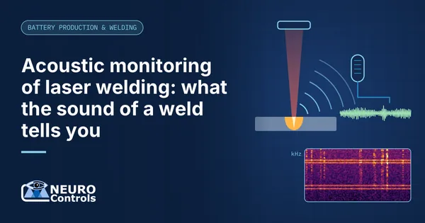
Acoustic sensing deserves a note because it sees something the optical methods struggle with. The keyhole and melt pool oscillate, and those oscillations radiate sound. In the Basile study, sound power measured with an optical microphone correlated with laser power with a coefficient of 0.95 at zero gap and strongly negatively with gap (-0.797), and a spectral peak around 63 kHz was linked to stable keyhole formation. An earlier Scientific Reports paper by Shevchik et al. combined structure-borne acoustic emission with back-reflected laser light and used synchrotron X-ray imaging as ground truth to classify conduction, keyhole, blowout and pore events in aluminium. The details of acoustic monitoring will get their own post on what the sound of a laser weld tells you.
How to choose an inspection combination
No single method covers the defect list above. A practical way to choose:
- List the defects by consequence. Piercing into the can and lack of connection usually rank highest, because one is a safety risk and the other an early field failure.
- Measure the gap before welding. Gap is the dominant cause of lack of connection, and it is cheap to measure.
- Pick one in-process method that sees depth or keyhole stability, such as OCT or acoustics, and one that sees the surface, such as a camera.
- Keep a precise post-process resistance check as a gross-failure filter and as one indicator of strength, not as the only quality criterion.
- Calibrate against destructive tests. Cross-sections and peel or shear tests on a sample of joints are the ground truth that every inline signal must be validated against.
- Store per-joint results with the module identifier, so that later failures can be traced. This also prepares you for the data questions raised by the EU battery passport from 2027.
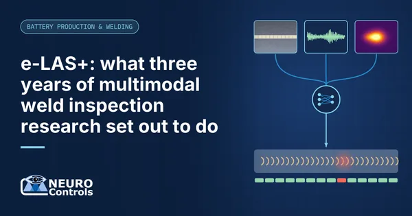
Combining sensors is where the gain is. Each modality sees a different physical aspect of the same event: light emission, geometry, depth, sound. Our introduction to what multimodal sensing means for industrial engineers explains the general principle, and the comparison of vision, thermal, depth, sound and vibration sensors covers what each one misses.
Where NeuroControls fits
Since May 2023 we have been a partner in the e-LAS+ research project with Fraunhofer IDMT, on machine-learning-based multimodal inline inspection of laser weld seams in battery cell production, with demonstration on a pilot plant. The project partners met at Fraunhofer IDMT in Ilmenau for the final months of e-LAS+. According to the Fraunhofer IDMT project page, the project period was May 2023 to April 2026.
The measurement chain from this work feeds into our Process Monitoring Kit, which combines the Edge AI Hub with an Acoustic Node and a Vision Node, optionally with vibration, and is built to order. A model trained on your data grades each joint and reports; it does not steer the laser and never sits in the weld control loop; the machine's controller stays untouched. Details are on the kits page and the battery production page. Background on our research projects is on the research overview.
Frequently asked questions
What are the most common laser welding defects in battery cells?
The defects that matter most are lack of fusion, lack of connection when the melt cannot bridge a gap, excessive penetration that pierces the cell can, porosity, spatter and brittle intermetallic layers in copper-aluminium joints. Piercing is a safety risk because it can lead to electrolyte leakage, while lack of connection often causes early failures in the field.
Why is laser welding copper to aluminium difficult for battery tabs?
Copper and aluminium form brittle intermetallic phases when they mix in the melt. Joint strength is highest with low intermixing, so penetration depth must be controlled tightly. Copper is also highly reflective, which makes energy coupling difficult. Green laser sources and beam oscillation strategies are among the approaches studied to improve coupling and control mixing.
Can a resistance measurement verify a battery laser weld?
Only partly. Resistance checks catch missing or grossly defective joints and are standard in module assembly. In a study on green laser welds of copper to aluminium battery tabs, resistance varied by less than 13 % across all parameter sets but did correlate with tensile strength. A precise resistance measurement is therefore a useful indicator, but it does not show the joint's metallurgy on its own, so it should be combined with in-process monitoring and validated against destructive tests.
How can weld penetration depth be monitored inline?
Optical coherence tomography measures keyhole depth directly through the welding optics, though it needs recalibration when process parameters change. Acoustic sensing captures keyhole oscillations that correlate with energy input and gap. Cameras see the surface but not the depth. Many lines combine a depth-sensitive method with surface inspection.
Which standard covers laser weld imperfections in aluminium and copper?
ISO 13919-2:2021 sets requirements and recommendations on quality levels for imperfections in electron and laser beam welded joints in aluminium, magnesium and their alloys and pure copper. It applies to material 0.5 mm thick or greater and covers visual examination, so thin battery connectors usually need additional, manufacturer-specific acceptance criteria.
Sources and further reading
- Das, Li, Williams, Greenwood (2018): Joining technologies for automotive battery systems manufacturing, World Electric Vehicle Journal 9(2) 22
- Basile et al. (2025): Monitoring part-to-part gap and laser power effects in remote laser welding of 1050 aluminum busbar-to-terminal connections via optical microphone sensing, Optics and Laser Technology 192
- Kaufmann et al. (2023): Seam properties of overlap welding strategies from copper to aluminum using green laser radiation for battery tab connections, Materials 16(3) 1069
- Shevchik et al. (2020): Supervised deep learning for real-time quality monitoring of laser welding with X-ray radiographic guidance, Scientific Reports 10, 3389
- ISO 13919-2:2021 Electron and laser-beam welded joints, quality levels for imperfections, part 2
- PEM RWTH Aachen and VDMA: Montageprozess eines Batteriemoduls und -packs (3rd edition, 2018)
- Fraunhofer IDMT: e-LAS+ project page